Machine tool, tool unit, and machining method

Inactive Publication Date: 2017-07-13
MURATA MASCH LTD
View PDF1 Cites 3 Cited by
  • Summary
  • Abstract
  • Description
  • Claims
  • Application Information

AI Technical Summary

Benefits of technology

The present invention provides a machine tool that allows for easy replacement of tool units, such as rotary tools, and a machining method that uses a tool unit with a drive transmission. The apparatus is designed so that the base of the tool unit is easily mounted and demounted from the tool post, allowing for quick replacement with another type of tool. The use of the drive transmission in the base allows for efficient use of power and prevents waste when using a rotation motor to drive the tool. The method of machining using the tool unit is efficient and the cutting tool is easy to replace. Overall, the invention simplifies the process of replacing and using different tools, making it faster and more convenient for users.

Problems solved by technology

However, the tool unit disclosed in Japanese Patent No. 2013-244582 has a problem that the drive transmission is disposed in the tool post and therefore demounting it from the tool post is troublesome and the replacement of a tool takes time.
Also, this tool unit has another problem that, during mounting, for example, a rotary tool (such as a drill) on the tool post, a path for transmitting the rotational driving force is ensured by demounting the tool unit and mounting the rotary tool in the position of the tool unit, and therefore only one of the tool unit and the rotary tool can be mounted on the tool post.

Method used


Image

  • Machine tool, tool unit, and machining method
  • Machine tool, tool unit, and machining method
  • Machine tool, tool unit, and machining method

Examples


Embodiment Construction

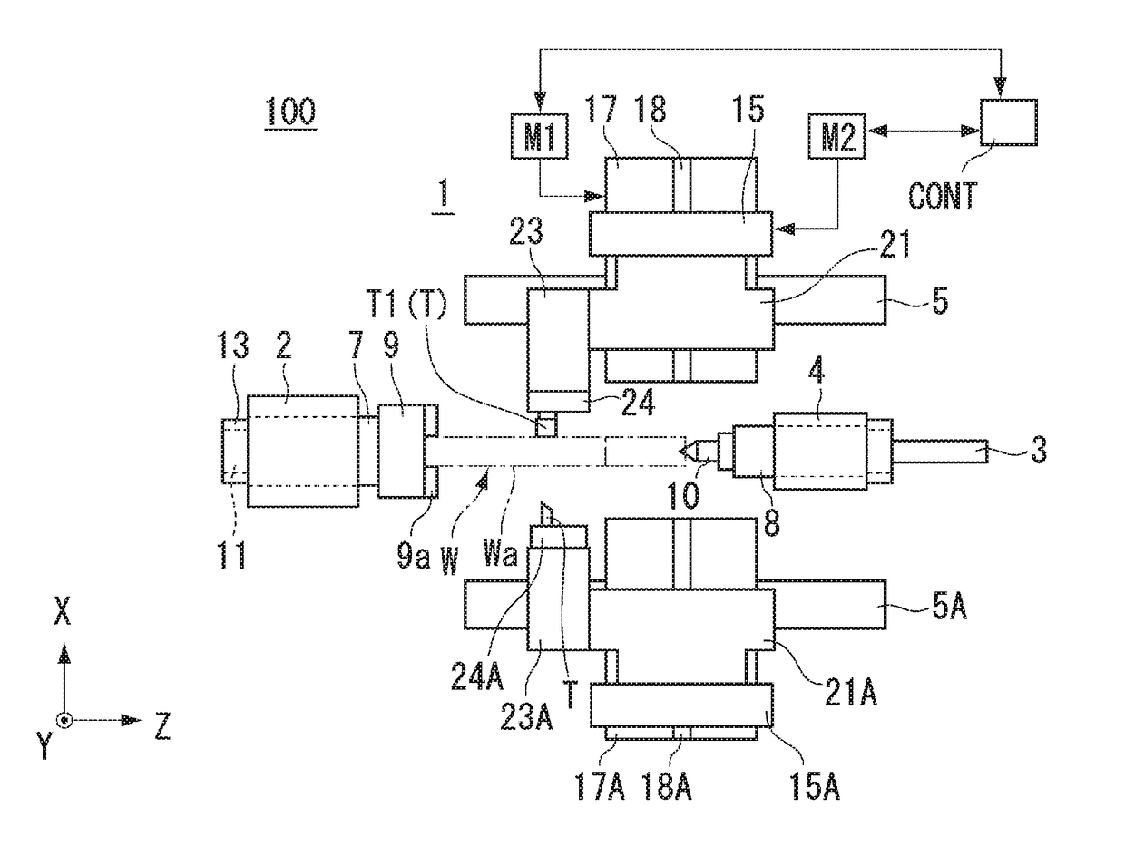
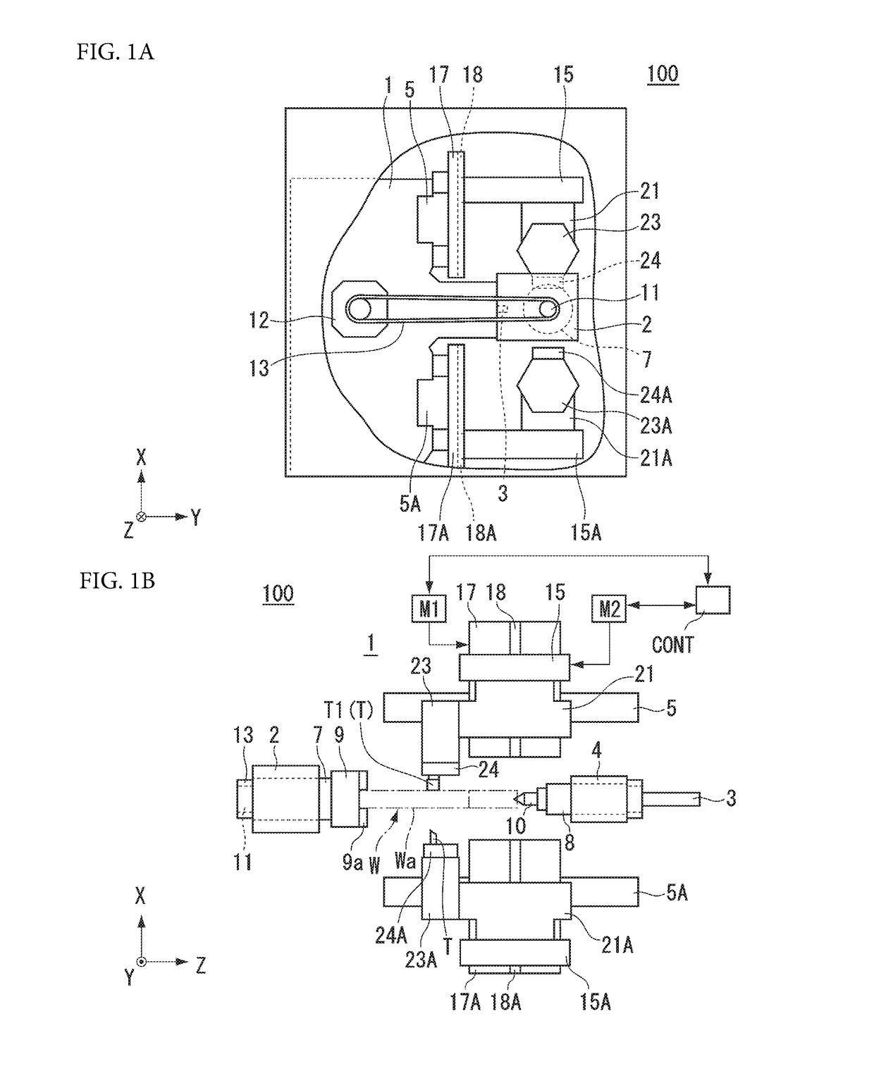
[0023]Now, preferred embodiments of the present invention will be described with reference to the drawings. However, the present invention is not limited thereto. To clarify the preferred embodiments, the drawings are scaled, for example, partially enlarged or highlighted, as necessary. In the drawings, directions are shown by an XYZ coordinate system. In this XYZ coordinate system, a plane parallel or substantially parallel with the horizontal plane is defined as a YZ plane; the direction of the rotation axis of a main spindle 7 (a counter spindle 8) in the YZ plane is defined as a Z-direction; the direction perpendicular or substantially perpendicular to the Z-direction in the YZ plane is defined as a Y direction; the direction perpendicular or substantially perpendicular to the YZ plane is defined as an X direction; and the X axis is a direction that is perpendicular or substantially perpendicular to the Z-direction and determines the amount of cutting of a workpiece. In the draw...


PUM


Abstract

A tool unit includes a base that is mountable on and demountable from a first turret, a slider that is disposed on the base, holds a cutting tool in a state in which a direction of the linear cutting blade of the cutting tool is inclined with respect to a Z-direction by a predetermined angle when seen from an X-direction, and is able to move in a Y-direction perpendicular or substantially perpendicular to both the X-direction and Z-direction, and a drive transmission that is disposed on the base and is connected to a tool drive unit to move the slider.

Description

BACKGROUND OF THE INVENTION[0001]The present invention relates to a machine tool, a tool unit, and a machining method.[0002]2. Description of the Related Art[0003]A lathe, which is a machine tool, holds a workpiece to be machined, on the rotating shaft (spindle) and performs cutting or the like on the workpiece using a cutting tool while rotating the workpiece. Examples of a machining method using a lathe include a method of cutting a workpiece while feeding a cutting tool in a tangential direction of the workpiece (a direction crossing the rotation shaft). This machining method requires a drive system for moving the cutting tool in the tangential direction of the workpiece. For example, a known configuration of a tool unit includes a drive transmission for moving a cutting tool in a tangential direction of a workpiece that is formed in a tool post (for example, see Japanese Patent No. 2013-244582).[0004]However, the tool unit disclosed in Japanese Patent No. 2013-244582 has a probl...

Claims


Application Information

Patent Timeline
IPC IPC(8): B23B29/24
CPCB23B29/246B23B29/205B23B29/248B23B1/00B23B3/168B23B2260/07B23B3/161B23B7/04B23B29/24B23Q3/155B23B2210/02
Inventor ISHIHARA, TADASHI
Owner MURATA MASCH LTD
Why Eureka
Try Eureka