Multi-channel network-on-a-chip

a multi-channel network and chip technology, applied in the field of electronic devices, can solve problems such as reducing the availability of systems or a portion of systems

Active Publication Date: 2020-09-01
NXP USA INC
View PDF71 Cites 2 Cited by
  • Summary
  • Abstract
  • Description
  • Claims
  • Application Information

AI Technical Summary

Problems solved by technology

However, such behavior typically results in a reduced availability of the system or a portion of the system, which may be undesirable.

Method used


Image

  • Multi-channel network-on-a-chip
  • Multi-channel network-on-a-chip
  • Multi-channel network-on-a-chip

Examples


Embodiment Construction

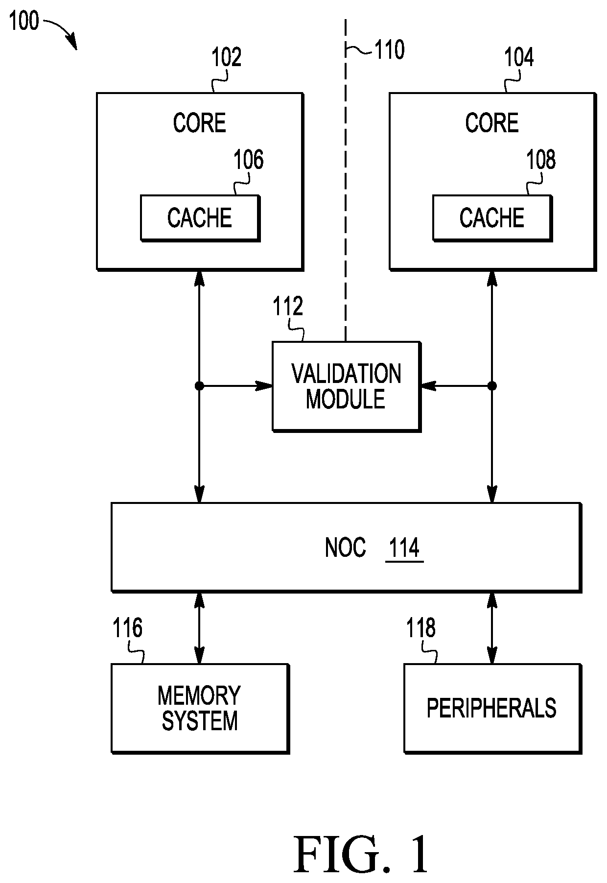
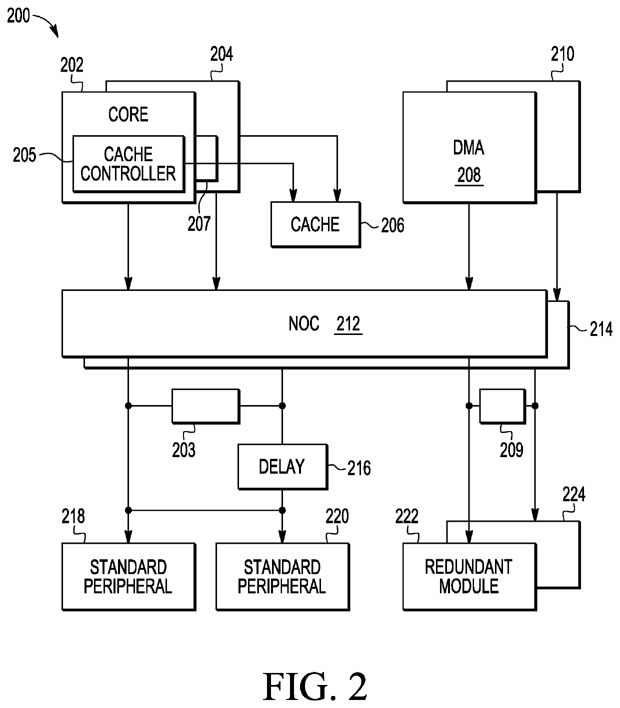
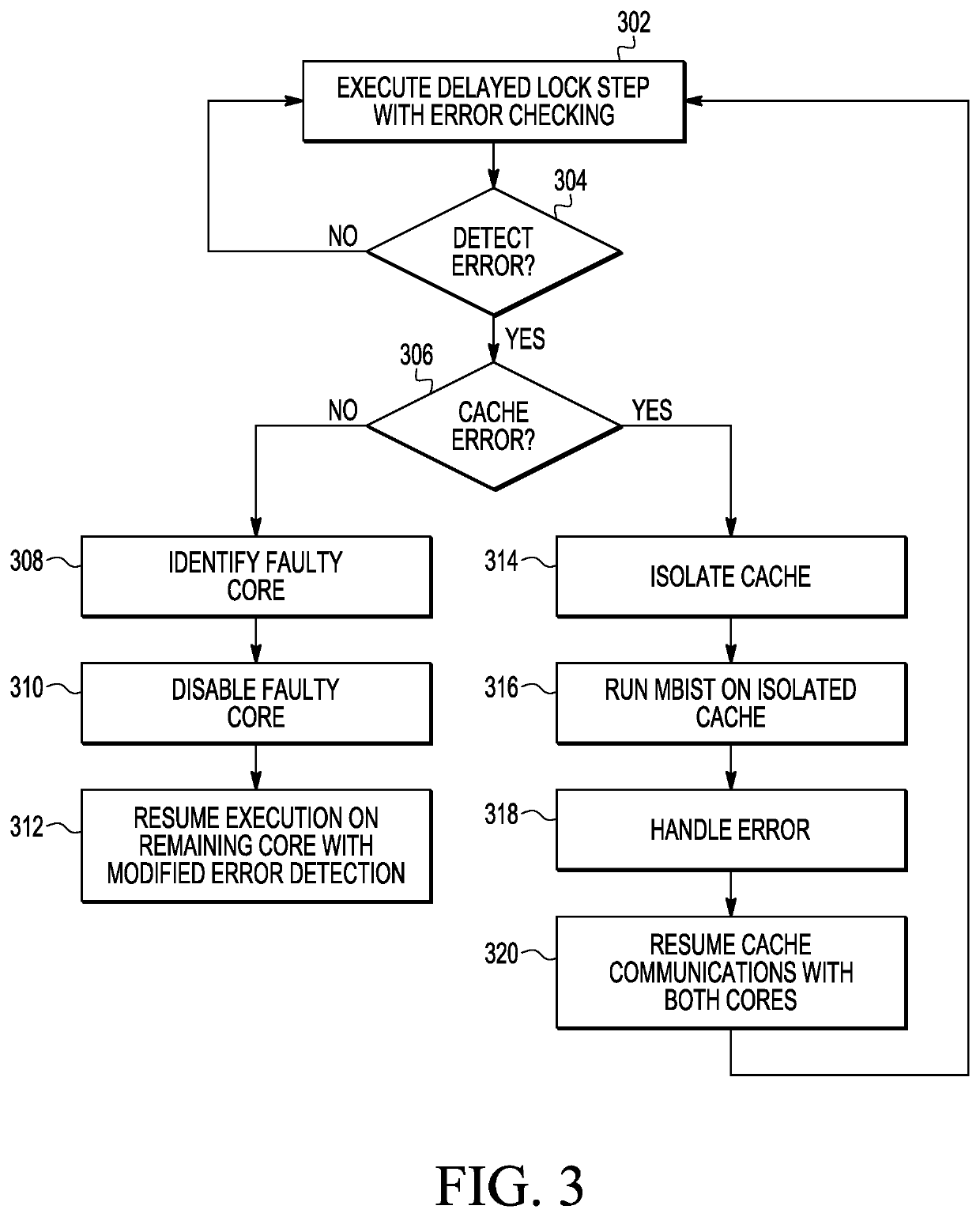
[0010]A fail-operational execution technique increases availability of a system using delayed lockstep execution by redundant channels including redundant processors that share local memory. Each of redundant channel detects errors in the local memory. The technique pauses execution in the redundant processors, corrects the errors in the local memory, and resumes execution, without a system reset. The fail-operational execution technique increases system availability as compared to a conventional systems including redundant local memory executing in lockstep going to a fail-safe configuration. The fail-operational execution technique does not trigger a system reset to handle synchronization errors in response to errors in local memory, and thus, has a reduced performance penalty to errors in the local memory. As referred to herein, errors include permanent errors in a device and soft errors in the device, which are random data errors caused by external stimulus (e.g., errors due to ...


PUM


Abstract

In at least one embodiment of the disclosure, a method includes detecting an error in a local memory shared by redundant computing modules executing in delayed lockstep. The method includes pausing execution in the redundant computing modules and handling the error of the local memory. The method includes resuming execution in delayed lockstep of the redundant computing modules in response to the handling of the error.

Description

FIELD OF THE INVENTION[0001]This disclosure relates to electronic devices and more particularly to fail-safe electronic devices.DESCRIPTION OF THE RELATED ART[0002]Safety requirements for exemplary applications international Standard IEC 61508 Safety integrity Levels used for automotive applications) require fail-safe electronics systems that prevent or mitigate unsafe consequences in response to detection of a system malfunction. Accordingly, system-on-a-chip (SoC) solutions are increasingly aware of safety issues. Timely detection of system failures allows an SoC to handle such faults or to configure the system in a safe state. However, such behavior typically results in a reduced availability of the system or a portion of the system, which may be undesirable. Accordingly, improved fail-safe processing techniques are desired.BRIEF DESCRIPTION OF THE DRAWINGS[0003]The present invention is illustrated by way of example and is not limited by the accompanying figures, in which like re...

Claims


Application Information

Patent Timeline
Patent Type & Authority Patents(United States)
IPC IPC(8): G06F11/16G06F11/07
CPCG06F11/165G06F11/1625G06F11/1641G06F11/1629G06F11/0796G06F11/1695G06F11/0793G06F11/073G06F2201/845
Inventor THANNER, MANFRED P.MUELLER, STEPHAN G.PALUS, ALEXANDRE P.REIPOLD, ANTHONY M.
Owner NXP USA INC
Why Eureka
Try Eureka