
Display device and method for controlling independently by a group of pixels

a display device and control method technology, applied in digital data authentication, instruments, computing, etc., can solve the problems of flicker phenomenon, difficult for the display driver integrated circuit to charge the pixels, and the integrated circuit may not have enough time to charge each of the pixels, so as to enhance the driving speed of the display. , the effect of clear screen

Active Publication Date: 2020-09-01
SAMSUNG ELECTRONICS CO LTD
View PDF67 Cites 0 Cited by
  • Summary
  • Abstract
  • Description
  • Claims
  • Application Information

AI Technical Summary

Benefits of technology

The patent aims to provide a user with a clear screen and enhance the display driving speed. This means that it improves the quality of the display and makes it faster to update.

Problems solved by technology

However, when the number of pixels increases, a display driver integrated circuit may not have enough time to charge each of the pixels.
As such, it may be difficult for the display driver integrated circuit to charge the pixels to the voltage level required by each of the pixels.
The voltage level lower than the voltage level required by each of the pixels may distort the screen or may cause a flicker phenomenon.
The increase of the data may slow the driving speed of the display.

Method used


Image

  • Display device and method for controlling independently by a group of pixels
  • Display device and method for controlling independently by a group of pixels
  • Display device and method for controlling independently by a group of pixels

Examples


Embodiment Construction

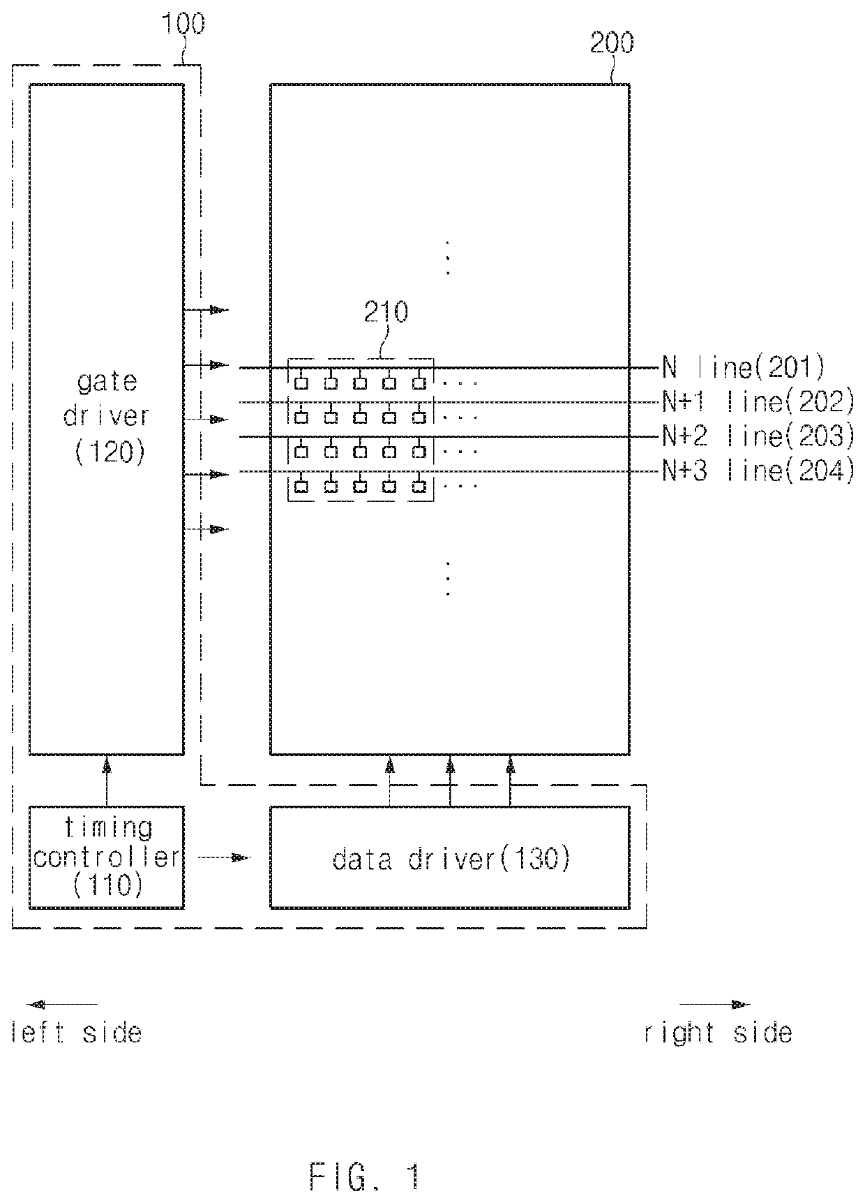
[0024]FIG. 1 illustrates a block diagram illustrating a display in which a display driver integrated circuit and a display panel are simplified, according to an embodiment. A display driver integrated circuit (DDI) (e.g., including display driving circuitry) 100 and a display panel 200 that are illustrated in FIG. 1 may be included in an electronic device 601 illustrated in FIG. 6.

[0025]Referring to FIG. 1, the DDI 100 may be electrically connected to lines disposed on the display panel 200. For example, the DDI 100 may be connected to gate lines 201, 202, 203, and 204 and data lines (not illustrated) (or pixel lines). The DDI 100 may transmit (e.g., forward) various kinds of signals through the gate lines 201, 202, 203, and 204 and the data lines and may cause pixels 210 connected to the gate lines 201, 202, 203, and 204 and the data lines to emit light or put pixels in a state to emit light (e.g., to display light).

[0026]According to an embodiment, the DDI 100 may include a timing...


PUM


Abstract

A display driver integrated circuit may include a controller configured to receive first image data from an application processor positioned outside the display driver integrated circuit and a data driver configured to receive the first image data from the controller.

Description

CROSS-REFERENCE TO RELATED APPLICATION[0001]This application is based on and claims priority under 35 U.S.C. § 119 to Korean Patent Application No. 10-2017-0151969, filed on Nov. 15, 2017, in the Korean Intellectual Property Office, the disclosure of which is incorporated by reference herein its entirety.BACKGROUND1. Field[0002]The present disclosure relates to a technology for charging pixels included in a display.2. Description of Related Art[0003]An electronic device, which is equipped with a display, such as a smartphone, a wearable device, or the like has been widely supplied as mobile communication technologies develop. A user may execute various functions such as a photo or video capturing function, a music or video file playing function, a game function, an Internet function, and the like through a screen output from the display.[0004]As the demand for clearer and cleaner screens increases, the display with high resolution (e.g., 2560×1440) has been distributed increasingly....

Claims


Application Information

Patent Timeline
Patent Type & Authority Patents(United States)
IPC IPC(8): G09G3/3233G06F21/44G09G3/3291G06F3/041G09G3/36
CPCG09G3/3233G09G3/3688G09G3/3291G09G2310/027G09G2310/0294G09G2320/0252G09G2320/0673G09G2330/021G09G2310/0286G09G2310/0291G09G2320/0247G06F3/0416G06F21/44G09G2310/0221G09G3/3666G09G2230/00G09G3/3275G09G2310/08G09G2300/0452G09G2300/0828
Inventor BAE, JONG KONKIM, DONG HWYHAN, DONG KYOONLEEHONG, YUN PYO
Owner SAMSUNG ELECTRONICS CO LTD
Learn More