[0014]The height adjustment mechanism may be configured to bear the load on the upper support block in the intermediate configuration. In other words, the intermediate configuration can be entered whilst a vessel is in place on the support structure. An advantage of the invention may be that the support structures can be replaced at very close to their original loading. Using the traditional method, blocks that were removed later in the removal sequence became progressively more loaded, making them even harder to remove.
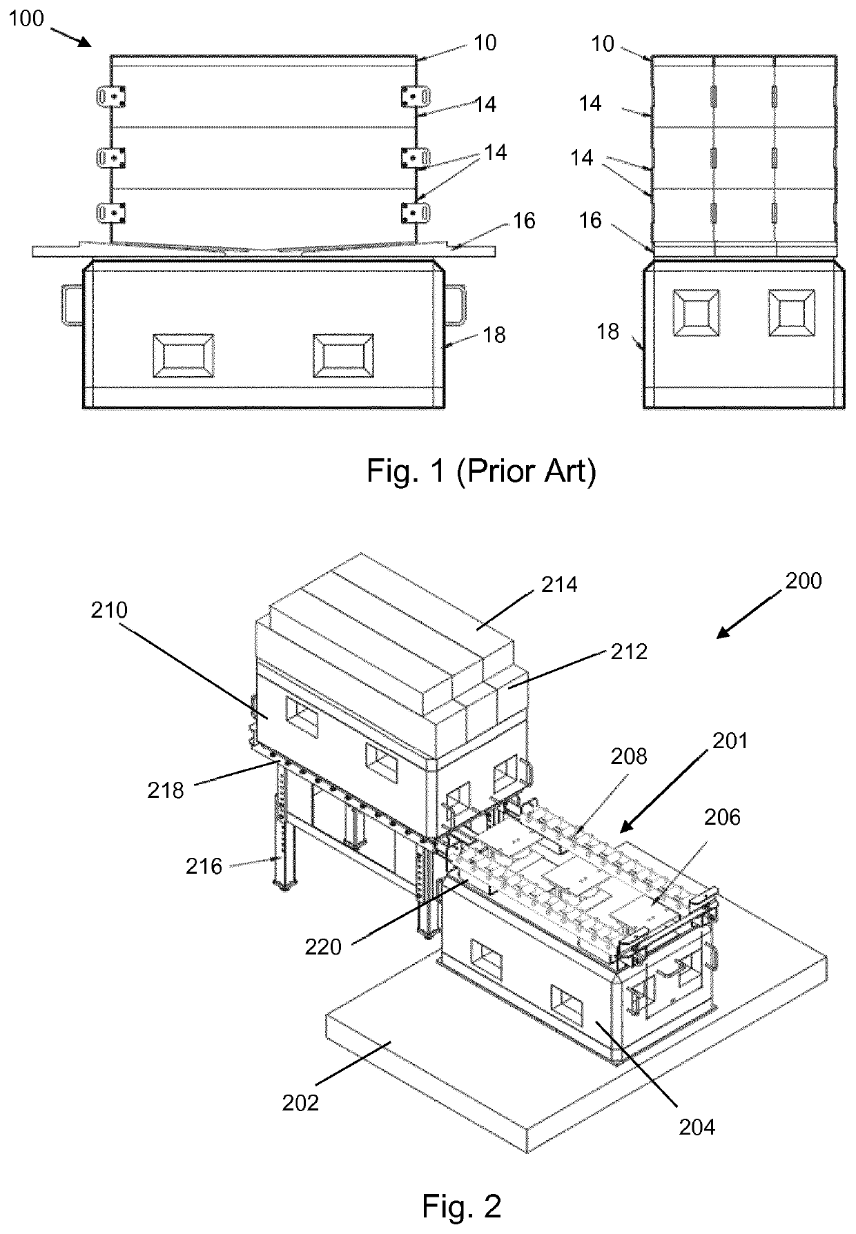
[0015]The support structure may be use existing dock furniture, e.g. the Type 1 support blocks discussed above, for the base support block and upper support block. The Type 1 block may be used in an inverted orientation for the upper support block. Thus, the base support block and / or the upper support block may comprise a cuboidal mass of reinforced concrete with a plated surface (e.g. a steel plate or the like) at an interface with the intermediate operating layer. The base support block and upper support block need to have the strength and durability associated with conventional dock furniture, i.e. the ability to support the loads associated with dry dock use and survive repeated submersion in sea water.
[0016]However, it may be desirable for the support structure of the invention to use support blocks that have a higher load capacity than conventional support blocks. This may enable hydrostatic testing of tanks to be performed whilst the vessel is in dry dock. In order to be compatible with existing dock furniture, it may be desirable for the higher load capacity support blocks to have substantially the same dimensions and weight as a conventional (e.g. Type 1) support block. In one example, this is achieved by fabricating the support block from a metal (e.g. steel) that exhibits the physical properties (in particular strength under compression) required. The support block may thus be formed from a plurality of rolled metal plates that are connected to form a block shape. In one example, the base support block and / or the upper support block may comprise: a lower plate that forms the bottom surface of the block; an upper plate that forms the top surface of the block; and a load bearing frame that connects the lower plate to the upper plate. The lower plate, upper plate and load bearing frame may be formed from steel. The lower plate and upper plate may have a width of 1.0 m and a length of 1.8 m. The support block may have a load capacity equal to or greater than 200 tonnes, preferably equal to or greater than 300 tonnes, and more preferably at least 400 tonnes.
[0017]The base support block and upper support block may have substantially the same size and weight. This can ensure that support structure is stable in the stacked configuration. To assist in preserving this stability, the components that are mountable in the intermediate operating layer may be arranged to have a flat profile. For example, the height adjustment mechanism may comprises hydraulic jacks that present a relatively large area footprint on both the base support layer and upper support layer. The height adjustment mechanism itself may be selected to minimise the normal vertical separation of the base support layer and upper support layer.
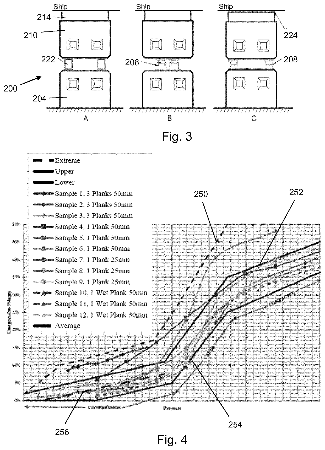
[0018]The contact layer may be formed from a material that is resiliently compressible under the expected range of pressures that it will experience in normal use. The contact layer may be a variable surface area in order to ensure that it operates in a pressure range where it is resiliently compressible. For example, the contact layer may comprise a plurality of selectively removable modular elements. In one example, the material of the contact layer is softwood. The modular elements may be planks or the like that are securable to the upper support block.
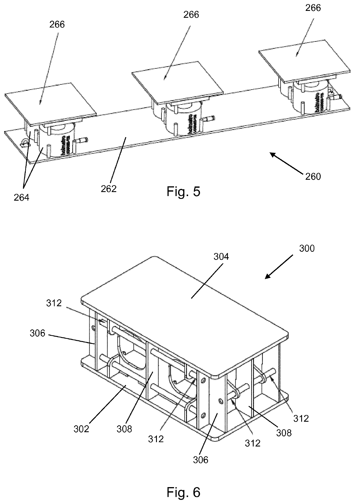
[0019]The height adjustment mechanism may comprise one or more jacking assemblies. For example, the height adjust mechanism may comprise a series of jacking assemblies mountable laterally along the intermediate operating layer, the jacking assemblies having a combined load capacity equal to or greater than a load capacity of the support structure in the load bearing configuration. Each jacking assembly may comprise one or more hydraulic jacks.

