Supercharge Your Innovation With Domain-Expert AI Agents!

Barrel harmonizing assembly and method

a technology of barrels and assemblies, applied in the direction of muzzle attachments, weapons, weapon components, etc., can solve the problems of time-consuming and hazardous loading techniques and firing tests, affecting the dwell time of the barrel, and complicated experimental techniques for determining the optimum internal ballistics. , to achieve the effect of tighter grouping of shots

Active Publication Date: 2020-09-08
HOWARD CHARLES M
View PDF10 Cites 1 Cited by
  • Summary
  • Abstract
  • Description
  • Claims
  • Application Information

AI Technical Summary

Benefits of technology

The present invention provides a harmonizing assembly for firearms that solves the problems of excessive noise, reduced accuracy, and difficulty in tuning the firearm. The assembly includes a cylindrical sleeve with threads, a first tuning nut, a second tuning nut, and a bonding agent. The cylindrical sleeve is placed around the barrel and the first and second tuning nuts are tightened to secure the assembly. The assembly also includes a threaded retainer to further secure the cylindrical sleeve. The harmonizing assembly helps to reduce noise, improve accuracy, and make it easier to tune the firearm.

Problems solved by technology

It is known that, in addition to affecting the accuracy of the rifle in other ways, the internal ballistics of a given cartridge affect its dwell time in the barrel, i.e., the time it takes for the bullet to exit the barrel after ignition.
Unfortunately, because the best ammunition loads for purposes of barrel harmonics can differ significantly even between otherwise identical rifles of the same model, complicated experimental techniques for determining the optimum internal ballistics of the ammunition must be performed for each individual rifle.
The hand loading techniques and firing tests required for this determination are time consuming and hazardous, and require experience and the purchase of expensive equipment.
Unfortunately, although some success has been achieved with these prior devices, the prior devices typically are attached to, and project a significant distance from, the forward end of the barrel so that the prior devices are prone to damage, present a significant obstruction on the end of the barrel, are prone to easily becoming out of tune, must be frequently retuned, and obstruct the use of a flash hider, suppressor, recoil compensator, or other external device on the end of the barrel which could further improve the accuracy of the barrel and / or provide other benefits.

Method used


Image

  • Barrel harmonizing assembly and method
  • Barrel harmonizing assembly and method

Examples


Embodiment Construction

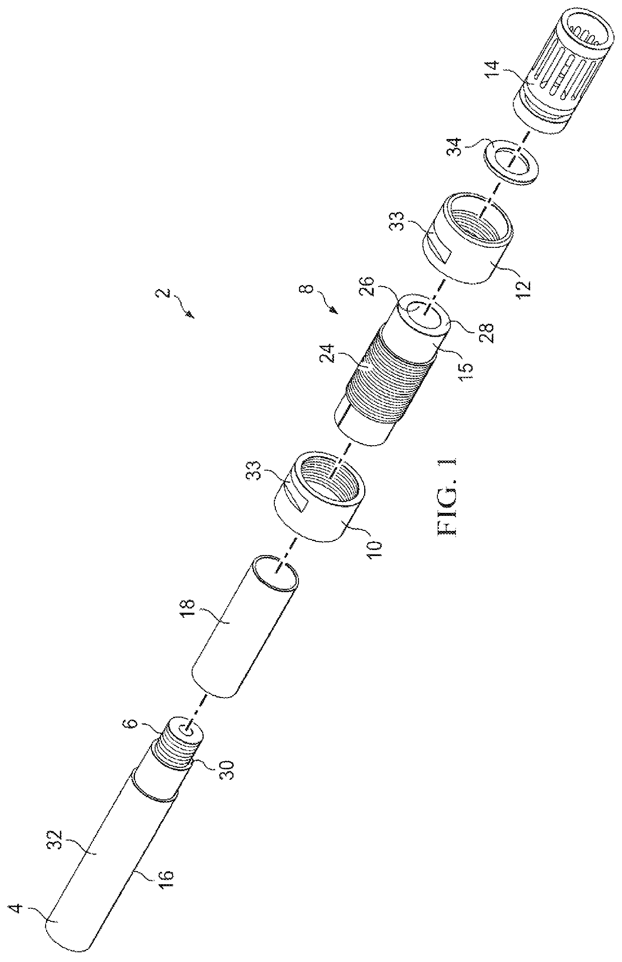
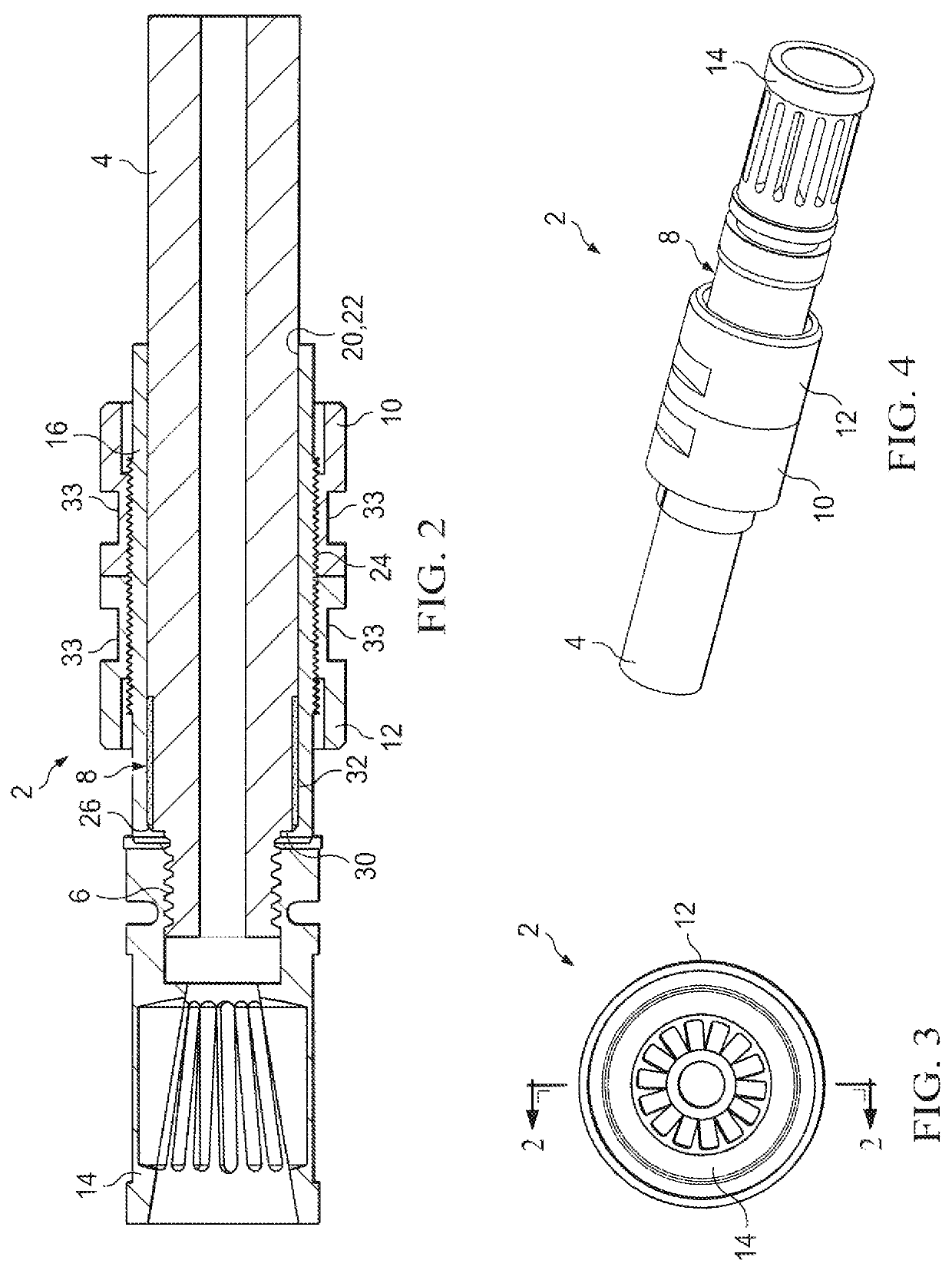
[0021]An embodiment 2 of the inventive barrel harmonizing assembly is illustrated in FIGS. 1-4. The inventive barrel harmonizing assembly 2 can be installed and used on generally any rifle or other firearm of a type where the barrel 4 of the firearm has, or is modified to have, a forward end segment 6 which (a) has a smaller outer diameter than the remainder of the barrel 4 and (b) is externally threaded.

[0022]The inventive barrel harmonizing assembly 2 preferably comprises: a cylindrical harmonizer sleeve 8 which is positioned around but preferably does not extend forwardly beyond the forward end of the barrel 4; a first tuning nut 10 which is threadedly received around, and is longitudinally repositionable along, the longitudinal exterior 15 of the cylindrical sleeve 8; a second tuning nut 12 which is threadedly received around, and is longitudinally repositionable along, the longitudinal exterior 15 of the cylindrical sleeve 8; a threaded retainer 14 which is threadedly received ...


PUM


Abstract

A barrel harmonizing assembly and method for a firearm in which a cylindrical harmonizer sleeve, as well as a pair of tuning nuts which are threadedly positioned on the harmonizer sleeve for longitudinal tuning movement, are positioned around the barrel, rather than projecting from the forward end of the barrel, in order to provide improved tuning and to permit the use, as part of the assembly, of a flash hider, a recoil compensator, a suppressor or other device on the end of the barrel to further improve the accuracy of the barrel and / or provide other benefits.

Description

FIELD OF THE INVENTION[0001]The present invention relates to barrel harmonizing assemblies and methods for improving the accuracy of rifles and other firearms.BACKGROUND OF THE INVENTION[0002]Barrel harmonics refers to the manner in which the barrel of a rifle or other firearm whips, torques and contorts when tiring. The point in time at which the bullet exits the barrel will determine the discharge orientation of the muzzle relative to its rest position prior to firing. If the bullet exits the muzzle near a peak or valley in the barrel motion, the muzzle will be relatively stationary at the instant when the bullet leaves the barrel, and shot dispersion will be minimized. Once the barrel reaches the upper or lower limit of its travel (crest or trough), the barrel, for the briefest of moments, is completely stationary, allowing a bullet that exits at that exact moment to move straight ahead, although not directly in line with the barrel's at-rest position prior to firing.[0003]If, on...

Claims


Application Information

Patent Timeline
Patent Type & Authority Patents(United States)
IPC IPC(8): F41A21/44
CPCF41A21/44F41A21/32
Inventor HOWARD, CHARLES M.
Owner HOWARD CHARLES M
Features
  • R&D
  • Intellectual Property
  • Life Sciences
  • Materials
  • Tech Scout
  • Unparalleled Data Quality
  • Higher Quality Content
  • 60% Fewer Hallucinations
Learn More