
Operation device and control method thereof

a technology of operation device and control method, which is applied in the direction of mechanical control device, tactile signalling system, instruments, etc., can solve the problem of difficulty in dealing with a demand for further miniaturization, and achieve the effect of imparting a preferable operation feel to the operator

Active Publication Date: 2020-09-08
ALPS ALPINE CO LTD
View PDF27 Cites 0 Cited by
  • Summary
  • Abstract
  • Description
  • Claims
  • Application Information

AI Technical Summary

Benefits of technology

The solution provides a more comfortable operation feel by aligning the displayed and actual positions, enhancing user experience through precise load application and visual feedback, while eliminating the need for motors, allowing for miniaturization and reduced power consumption.

Problems solved by technology

This manual input device 800 is able to impart a preferable operation feeling; however, because the motor 810 is used, it is difficult to deal with a demand for further miniaturization.

Method used


Image

  • Operation device and control method thereof
  • Operation device and control method thereof
  • Operation device and control method thereof

Examples


first embodiment

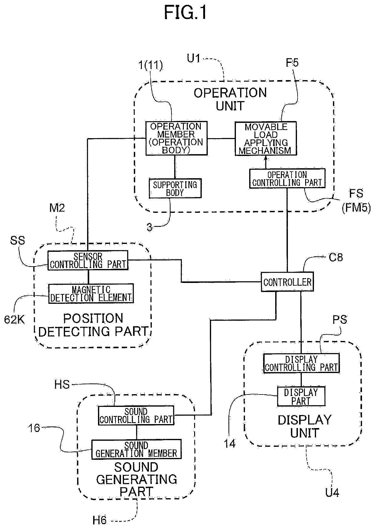
[0036]FIG. 1 is a block diagram illustrating a configuration of an operation device 100 according to a first embodiment.

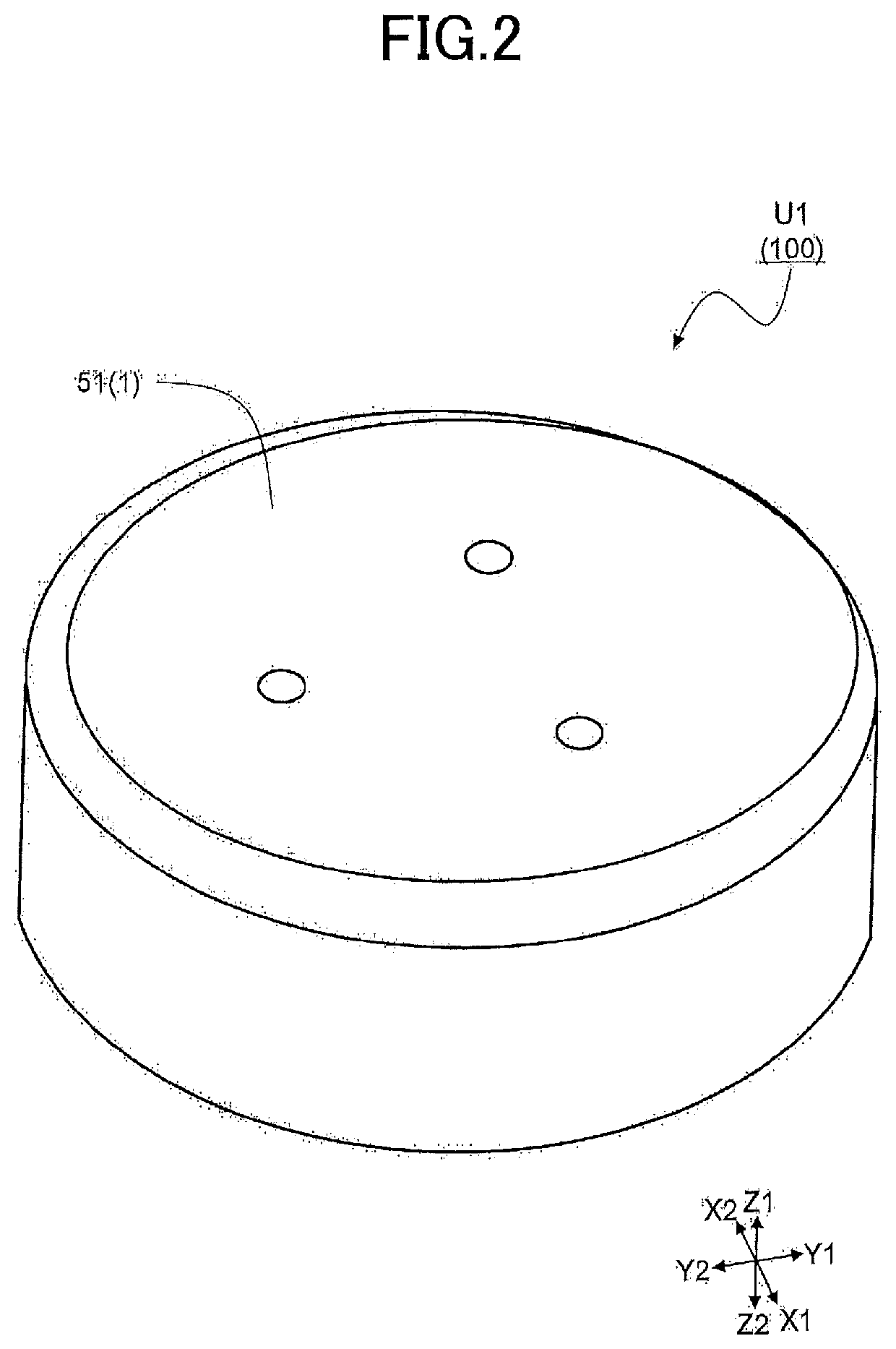
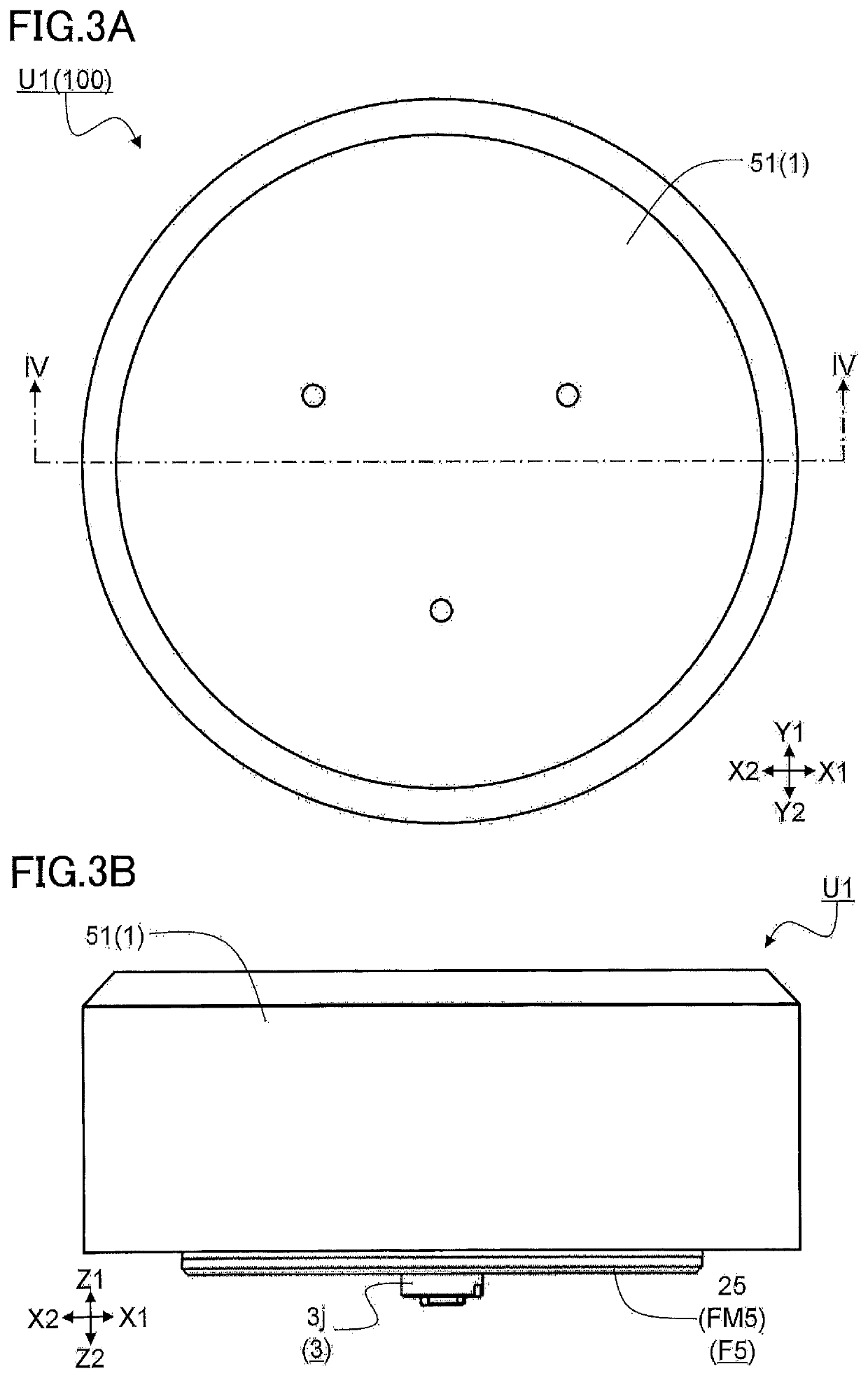
[0037]As illustrated in FIG. 1, the operation device 100 of the first embodiment includes an operation unit U1 having an operation body 11 operated by a manipulation of an operator, a position detecting part M2 for detecting a position of the operation body 11, a display unit U4 (refer to FIG. 14 to be described later) for displaying an operation position PP viewed by the operator, a sound generating part (not depicted in other figures, but denoted by H6 in the block diagram of FIG. 1) having a sound generating member (not depicted in other figures, but denoted by 16 in the block diagram of FIG. 1) for generating an electronic sound, and a controller (not depicted in other figures, but denoted by C8 in the block diagram of FIG. 1) electrically connected to each of the operation unit U1, the position detecting part M2, the display unit U4, and the sound generating p...

first modification

[0121]In the first embodiment, the operation unit U1 and the display unit U4 are arranged, but not limited to, at positions separated from each other; for example, the display unit U4 may be arranged in a vicinity of the operation unit U1 so that the operator is able to visually recognize both units U1 and U4.

second modification

[0122]In the first embodiment, the magnetic viscous fluid 75 is filled so as to fill an accommodation space (the accommodation space formed by the first yoke 15, the second yoke 25, and the sidewall spacer S17), in which the movable member 55 is accommodated. However, the present invention is not limited to this configuration, the magnetic viscous fluid 75 may be present in at least a part of the gap 5g.


PUM


Abstract

An operation device includes an operation unit including an operation body worked by an operator's manipulation; a position detecting part detecting a position of the operation body; and a display unit displaying a position of the operation body. The display unit includes an operation member, a supporting body, and a movable load applying mechanism including a movable member, a magnetic generating mechanism, a magnetorheological fluid, and an operation controlling part. The display unit includes a display part displaying the operation position. A display controlling part PS controls a display. A controller is included to control the operation controlling part and the display controlling part. In a control method of the operation device, the controller controls to display a state of the operation position of the operation body on the display part.

Description

CROSS-REFERENCE TO RELATED APPLICATIONS[0001]The present application is a continuation application of International Application No. PCT / JP2017 / 008060 filed on Mar. 1, 2017, which claims priority to Japanese Patent Application No. 2016-126476 filed on Jun. 27, 2016. The contents of these applications are incorporated herein by reference in their entirety.BACKGROUND OF THE INVENTION1. Field of the Invention[0002]The present invention relates to an operation device and a control method thereof, which impart an operation feeling to an operator when manipulated by the operator.2. Description of the Related Art[0003]Recent years, various input devices have been proposed with a force feedback function, which makes operation feeling preferable and ensures a desired operation by applying external force (force sense) such as resistance force and thrust corresponding to an operation amount and an operation direction of an operation member when an operator manipulates the operation member. In p...

Claims


Application Information

Patent Timeline
Patent Type & Authority Patents(United States)
IPC IPC(8): G05G5/03G09G3/36G08B7/06F16F9/12H01L43/04G06F3/01G05G25/00H01L43/06F16F9/53G05G1/08G06F3/0362G08B6/00G08B3/10H10N52/00H10N52/80
CPCG06F3/0362G05G1/08F16F9/12G06F3/016G06F3/01G09G3/36G05G25/00F16F9/535G08B7/06F16F9/53G05G5/03H01L43/06H01L43/04G08B6/00G08B3/10G05G2505/00G05G5/06G05G1/025H10N52/80H10N52/00
Inventor GOTO, ATSUSHITAKAHASHI, KAZUNARI
Owner ALPS ALPINE CO LTD
Learn More