
Recording Medium, Recording Method, and Computer Program

Inactive Publication Date: 2008-06-12
PIONEER CORP
View PDF9 Cites 2 Cited by
  • Summary
  • Abstract
  • Description
  • Claims
  • Application Information

AI Technical Summary

Benefits of technology

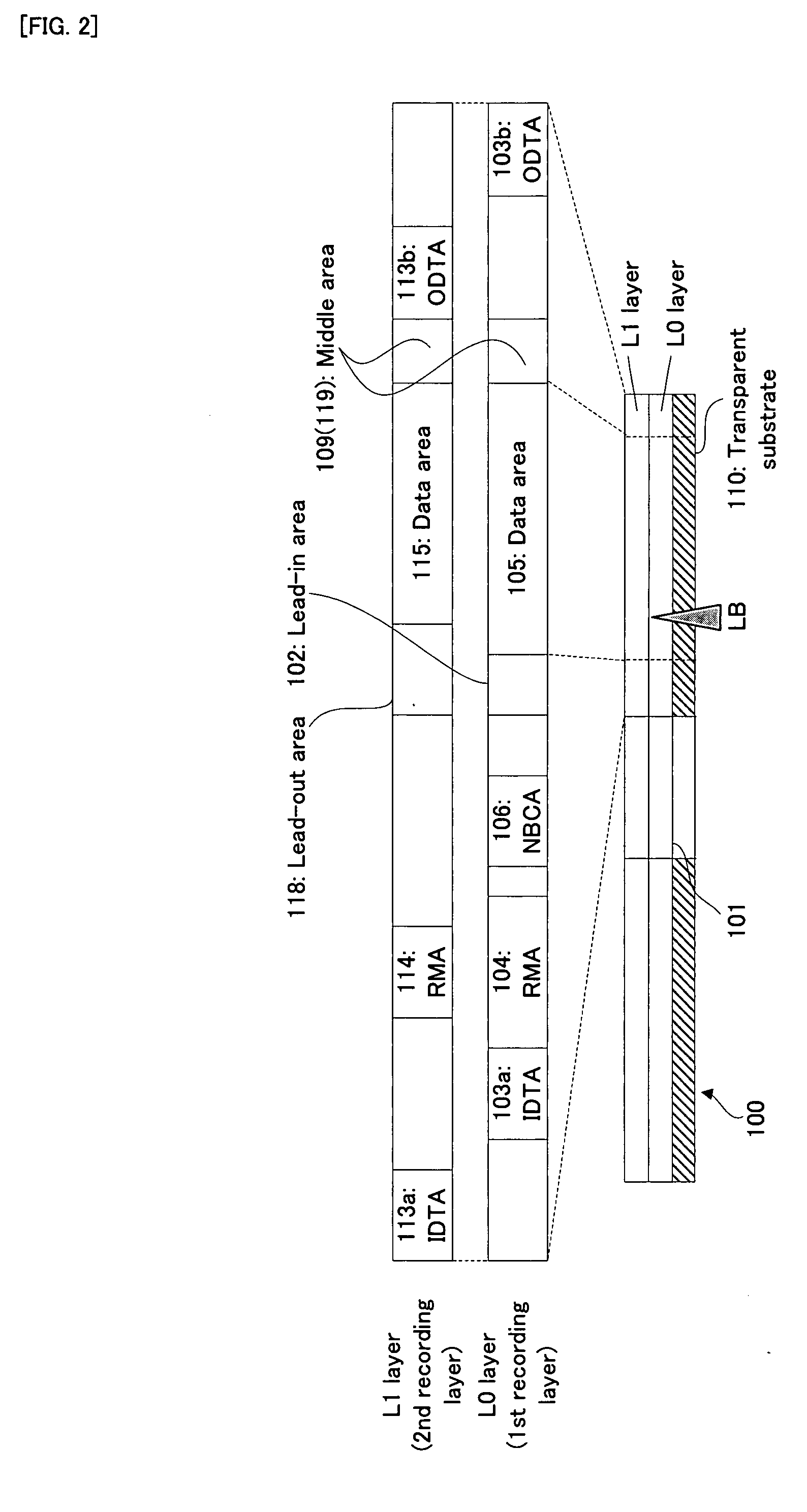
[0008]Particularly in the present invention, the distance between (i) the area portion in the second recording layer corresponding to the edge on the inner circumferential side of the control area in the first recording layer) and (ii) the edge on the outer circumferential side of the control area in the second recording layer) is larger than or equal to a first predetermined value or more. In other words, the inner radius of the control area in the first recording layer and the outer circumferential side of the control area in the second recording layer are away from each other by a first predetermined value or more. The term “corresponding to” herein indicates that it exists at a substantially facing or opposed position in design (e.g. at substantially the same radial position). In an actual recording medium, it is not necessarily located at the facing position due to an influence or the like in the production process. The term “face” herein indicates a relationship that two points are actually at the same radial position. For example, as discussed in detail in Detailed Description later, the inner radius of the control area in the first recording layer and the outer radius of the control area in the second recording layer are away from each other by a length corresponding to “0.4 mm+a tolerance length (relative tolerance)”. Thus, it is possible to secure a preferable recording operation or reproduction operation. In other words, it is possible to provide the preferable control area (i.e., the lead-in area and the lead-out area) which can secure the preferable recording operation or reproduction operation.
[0067]According to the computer program product of the present invention, the above-mentioned recording apparatus can be embodied relatively readily, by loading the computer program product from a recording medium for storing the computer program product, such as a ROM (Read Only Memory), a CD-ROM (Compact Disc-Read Only Memory), a DVD-ROM (DVD Read Only Memory), a hard disk or the like, into the computer, or by downloading the computer program product, which may be a carrier wave, into the computer via a communication device. More specifically, the computer program product may include computer readable codes to cause the computer (or may comprise computer readable instructions for causing the computer) to function as the above-mentioned recording apparatus.

Problems solved by technology

However, there is such a technical problem that if there is a too large interval between the edge on the inner circumferential side of the lead-in area and the edge on the outer circumferential side of the lead-out area, a recording capacity to record therein a user's data becomes small by that much.
On the other hand, there is also such a technical problem that if there is a too small interval between the edge on the inner circumferential side of the lead-in area and the edge on the outer circumferential side of the lead-out area, it is difficult or impossible to certainly secure a stable recording operation or reproduction operation.

Method used


Image

  • Recording Medium, Recording Method, and Computer Program
  • Recording Medium, Recording Method, and Computer Program
  • Recording Medium, Recording Method, and Computer Program

Examples


Embodiment Construction

[0090]Hereinafter, the best mode for carrying out the present invention will be discussed in order for each embodiment, with reference to the drawings.

Embodiment of Recording Medium

[0091]At first, with reference to FIG. 1 to FIG. 11, an optical disc as an embodiment according to the recording medium of the present invention will be discussed.

[0092](1) Basic Structure

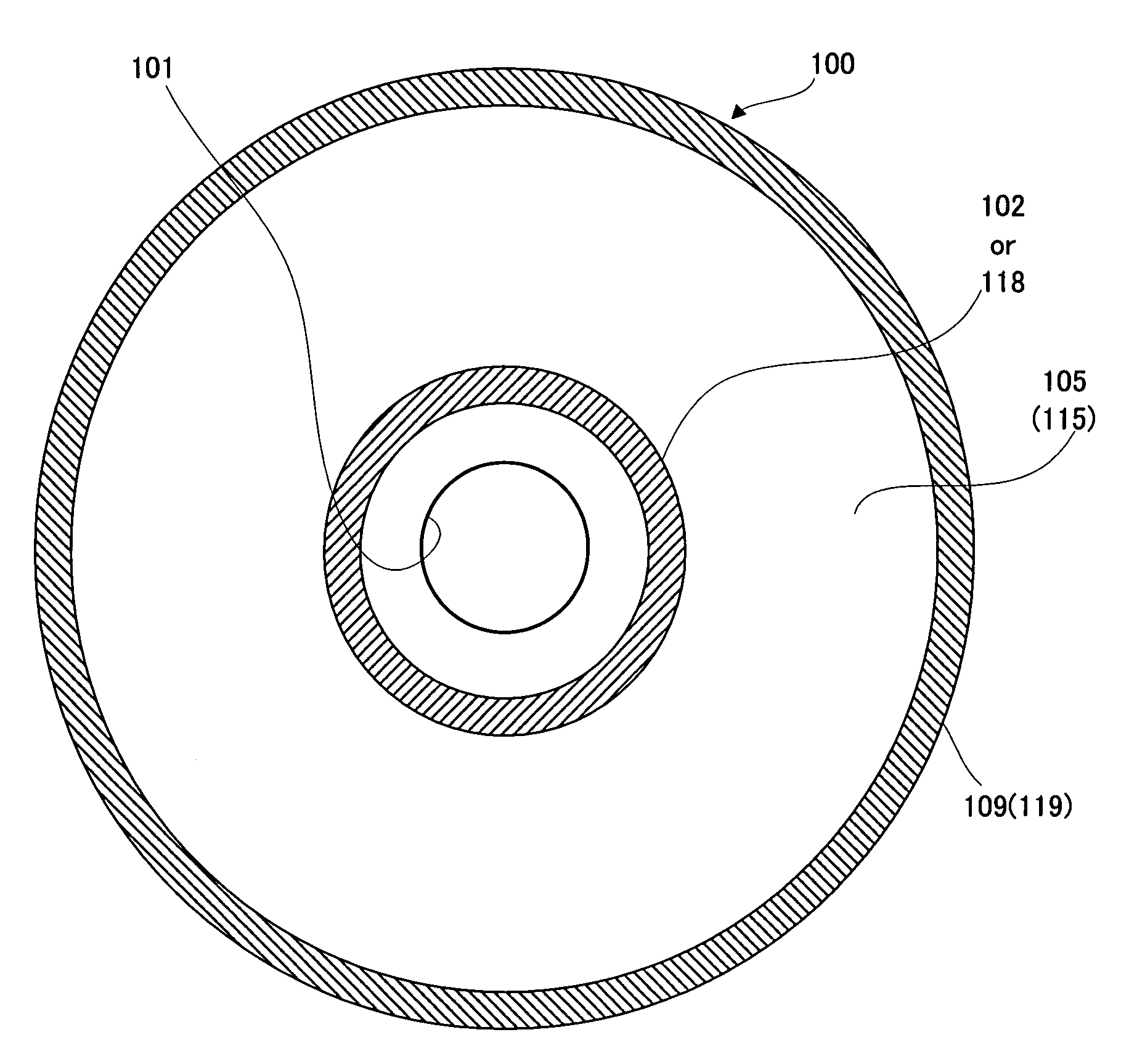
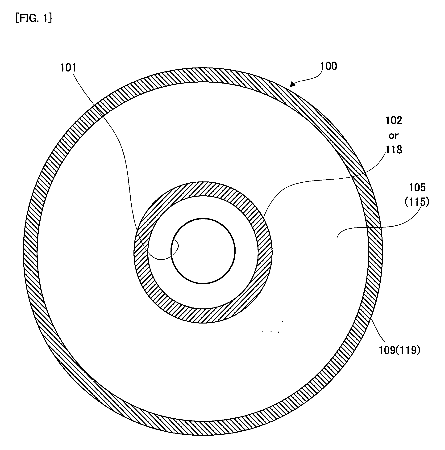
[0093]At first, with reference to FIG. 1 and FIG. 2, an explanation will be given to the basic structure of the optical disc as being an embodiment according to the recording apparatus of the present invention. FIG. 1 is a substantial plan view showing the basic structure of an optical disc 100 in the embodiment, and FIG. 2 is a schematic cross sectional view of the optical disc 100 and a corresponding conceptual diagram showing a recording area structure in the radial direction thereof.

[0094]As shown in FIG. 1, the optical disc 100 has a recording surface on a disc main body with a diameter of about 12 cm, as is a DVD. ...


PUM


Abstract

A recording medium (100) is provided with a first recording layer (L0) and a second recording layer (L1) for recording information. The first recording layer and the second recording layer are provided with control areas (102, 118), respectively, for recording control information for controlling at least recording or reproduction of the recording information. An area portion of the second recording layer which corresponds to an end portion on an inner circumference side of the control area in the first recording layer, and an end portion on an outer circumference side of the control area in the second recording layer are separated by a prescribed value or more.

Description

TECHNICAL FIELD[0001]The present invention relates to a recording medium, such as a DVD, a recording apparatus and method, such as a DVD recorder, and a computer program which makes a computer function as the recording apparatus.BACKGROUND ART[0002]In an information recording medium, such as a CD-ROM (Compact Disc-Read Only Memory), a CD-R (Compact Disc—Recordable), and a DVD-ROM, for example, as described in patent documents 1 and 2 or the like, there is also developed an information recording medium, such as a multi-layer type or dual-layer type optical disc, in which a plurality of recording layers are laminated or pasted on the same substrate. Then, on an information recording apparatus, such as a DVD recorder, for performing the recording with respect to the dual-layer type optical disc, laser light for recording is focused on a recording layer located on the front (i.e. on the closer side to an optical pickup) as viewed from the irradiation side of the laser light (hereinafter...

Claims


Application Information

Patent Timeline
IPC IPC(8): G11B3/74
CPCG11B7/0037G11B7/00736G11B2007/0013G11B20/1217G11B7/24038G11B7/007G11B7/0045
Inventor OMORI, KYUSHOKATO, MASAHIROKAWANO, EISAKUMIURA, MASAHIROKANEGAE, TOHRU
Owner PIONEER CORP
Learn More