High current DC dispersing and converging connector

a dc dispersion and connector technology, applied in the direction of coupling contact members, coupling device connections, securing/insulating coupling contact members, etc., can solve the problems of fixed connection between the sheath ii and the sheath ii, and achieve the effect of more accurate and firm positioning

Active Publication Date: 2020-09-08
SHENZHEN TAIGELAI PRECISION ELECTRONICS
View PDF5 Cites 0 Cited by
  • Summary
  • Abstract
  • Description
  • Claims
  • Application Information

AI Technical Summary

Benefits of technology

[0008]With the technical solution of the disclosure, the following technical effects are produced: 1. the convergence and connection of multi-point dispersed current can be realized; and 2. the convergence box is avoided, and a connection space is saved; processing is more convenient, and processing time is also reduced.
[0010]In a further improvement, the high current DC dispersing and converging connector further comprises a positioning clamping block; the positioning clamping block is provided with a positioning part I and a positioning part II; the positioning part I is clamped and fixed on the connecting end I which is in the same horizontal plane as the connecting end II; and the positioning part II is clamped and fixed on one of the other two connecting ends I. The design of the positioning clamping block can effectively prevent the connecting end I from being tilted and deformed after the connector is inserted and unplugged for multiple times, thereby ensuring the connection effect of the connector.
[0011]In a further improvement, the positioning clamping block is also provided with a positioning clamping plate; and the positioning clamping block is fixed into the sheath I through the positioning clamping plate. The positioning clamping plate is designed so that the positioning clamping block can be better clamped among the two connecting ends I and the sheath, thereby realizing more accurate and firmer positioning.

Problems solved by technology

Once an error is generated, the sheath I and the sheath II cannot be inserted into and fixedly connected due to the arrangement of the fool-proof convex strip.

Method used


Image

  • High current DC dispersing and converging connector
  • High current DC dispersing and converging connector

Examples


Embodiment Construction

[0015]The preferred embodiments of the disclosure are further described below with reference to the drawings.

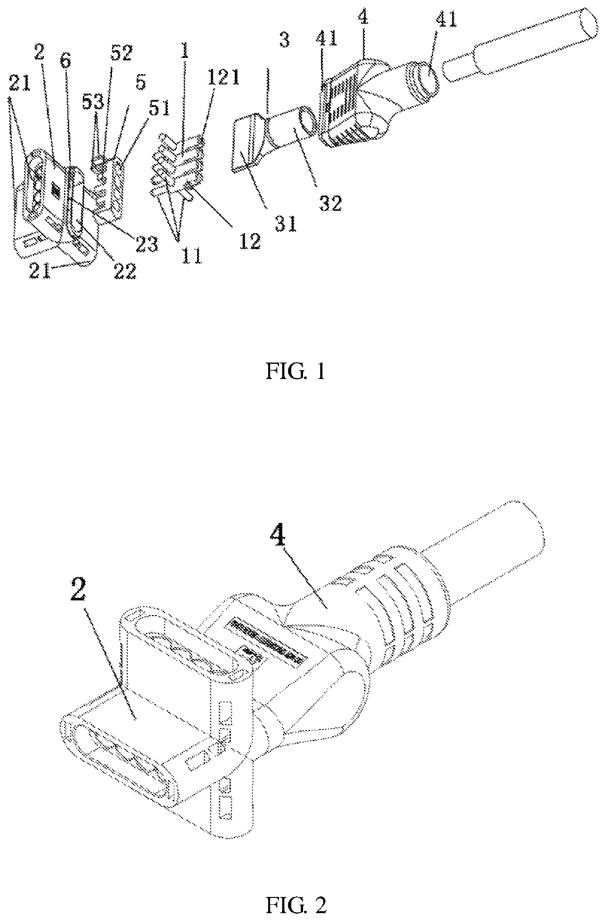
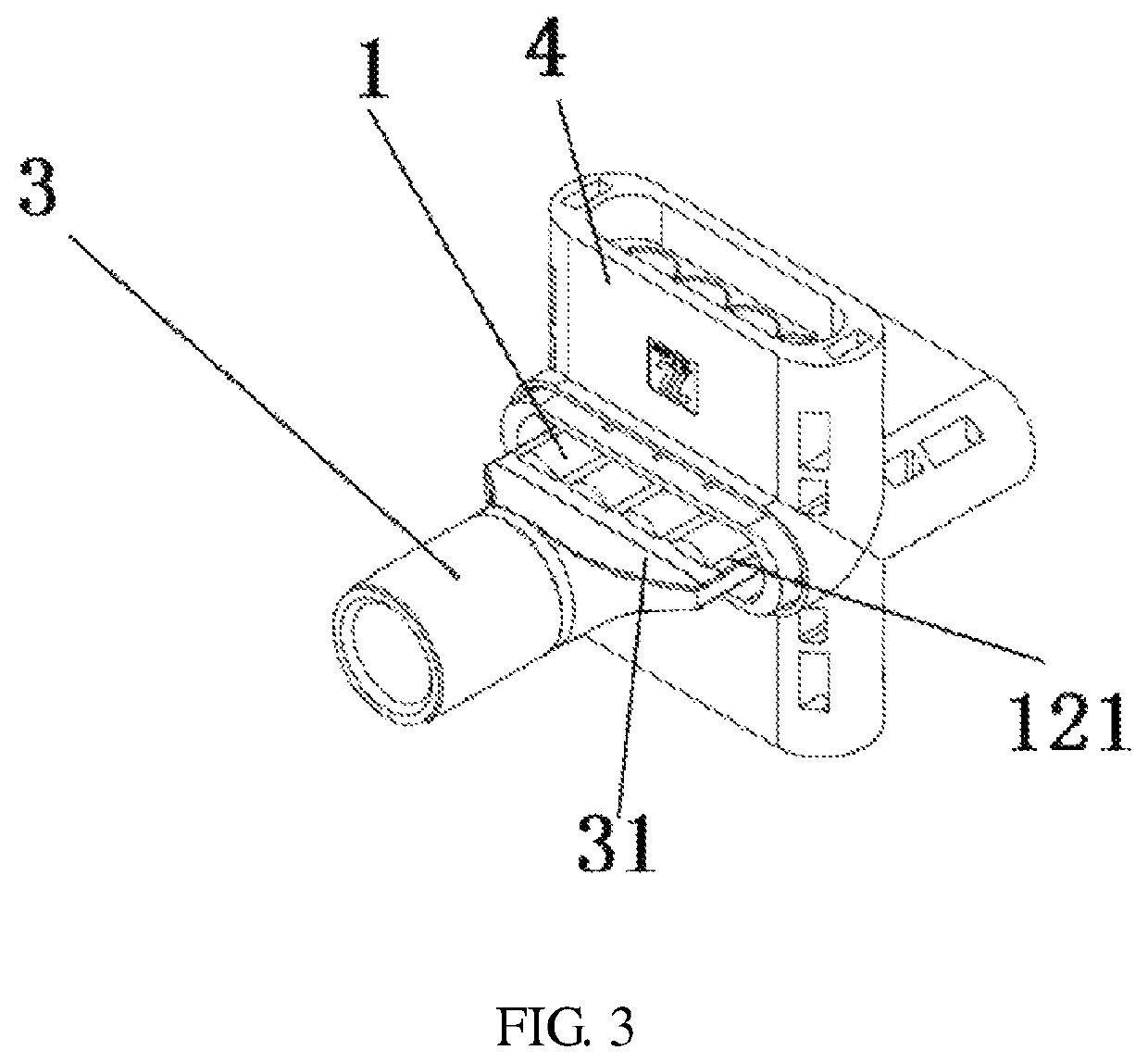
[0016]As shown in FIG. 1 to FIG. 3, a high current DC dispersing and converging connector comprises a dispersing and connecting terminal 1, a sheath I 2, a converging and connecting terminal 3, a sheath II 4 and a positioning clamping block 5.

[0017]The dispersing and connecting terminal comprises three connecting ends I 11 and a connecting end II 12; one connecting end I and the connecting end II are in the same horizontal plane; the other two connecting ends I are symmetrically fixed to the connecting end II; the sheath I 2 is provided with three inserting ports I 21 and an inserting port I 22; the sheath I is sleeved on an outer surface of the dispersing and connecting terminal; the three connecting ends I of the dispersing and connecting terminal are respectively arranged in the three inserting ports I; the tail of the connecting end II 12 is provided with an inserting gro...


PUM


Abstract

A high current DC dispersing and converging connector comprises a dispersing and connecting terminal, a sheath I, a converging and connecting terminal and a sheath II, the dispersing and connecting terminal comprises three connecting ends I and a connecting end II; two connecting ends I are symmetrically fixed to the connecting end II; the sheath I is provided with three inserting ports I and an inserting port II; the sheath I is sleeved on an outer surface of the dispersing and connecting terminal; the tail of the connecting end II is provided with an inserting groove; the converging and connecting terminal is an umbrella-shaped copper-aluminum terminal; the sheath II is provided with two connecting ports; the sheath II is sleeved on an outer surface of the converging and connecting terminal; when the umbrella-shaped end is inserted into and fixed with the inserting groove, the inserting port II of the sheath I is inserted into and fixedly connected with the connecting port of the sheath II; and a seal ring is arranged at a contact position where the inserting port II and the connecting port are contacted. By improving the structure of the existing high current DC single-input and single-output connector, the solution reduces the convergence box, saves a connection space, makes processing more convenient, and also reduces processing time.

Description

CROSS-REFERENCE TO RELATED APPLICATIONS[0001]This application claims priority to Chinese Patent Application No. 201811258916.1 with a filing date of Oct. 26, 2018. The content of the aforementioned applications, including any intervening amendments thereto, are incorporated herein by reference.TECHNICAL FIELD[0002]The disclosure relates to the field of connectors for solar panels, and particularly relates to a high current DC dispersing and then converging connector.BACKGROUND OF THE PRESENT INVENTION[0003]With the development of the society and the advancement of science and technology, environmentally-friendly and pure energy has gradually attracted human attention. As an environmentally-friendly and endlessly accessible new energy source, photovoltaics are valued by people. The photovoltaic panel is a common device for converting solar energy, and has high requirements for connectors during the use of the photovoltaic panel, which requires high electrical connection tightness, se...

Claims


Application Information

Patent Timeline
Patent Type & Authority Patents(United States)
IPC IPC(8): H01R25/16H01R13/03H01R13/52H01R13/64H01R13/502
CPCH01R13/64H01R25/161H01R13/502H01R13/03H01R13/5219H01R13/02H01R25/162H01R13/42H01R13/5202H01R31/02H01R2101/00
Inventor LUO, BAOJUN
Owner SHENZHEN TAIGELAI PRECISION ELECTRONICS
Why Eureka
Try Eureka