A device and method for adjusting the output voltage of a power supply circuit

A technology for outputting voltage and power supply circuits, which is used in output power conversion devices, regulating electrical variables, converting DC power input to DC power output, etc.

Active Publication Date: 2021-06-01
INSPUR SUZHOU INTELLIGENT TECH CO LTD
View PDF9 Cites 0 Cited by
  • Summary
  • Abstract
  • Description
  • Claims
  • Application Information

AI Technical Summary

Problems solved by technology

If the tolerance range of the load voltage level is relatively strict, the position of the feedback voltage will be connected to the load point in the application, so as to satisfy the load voltage level within the tolerance range, so a line is bound to be needed to connect the load and the load conversion In addition, this wire must ensure that the feedback voltage is accurate, and it must minimize passing through high-noise areas to avoid interference with the feedback voltage, which will inevitably result in waste of space and restrictions on wiring.

Method used


Image

  • A device and method for adjusting the output voltage of a power supply circuit
  • A device and method for adjusting the output voltage of a power supply circuit
  • A device and method for adjusting the output voltage of a power supply circuit

Examples


Embodiment 1

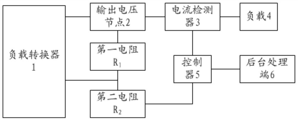
[0033] At present, the output voltage device of the power supply circuit is mainly a Buck power supply circuit, including a load converter 1. The load converter 1 refers to a device that converts the power supply voltage output by the power supply output terminal of the power supply to the power supply voltage required by the load 4, such as DC converter (DC / DC converter).

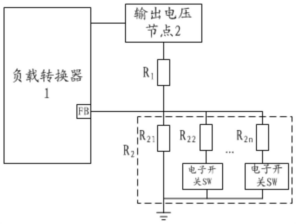
[0034] The output voltage node 2 of the load converter 1 is connected to the load 4 and the feedback circuit, and the feedback circuit includes a first resistor R 1 and the second resistor R 2 , the first resistor R 1 One end is connected to the output voltage node 2, and the other end is connected to the second resistor R 2 One end, the second resistor R 2 The other end is grounded, the first resistor R 1 and the second resistor R 2 The node between is connected to the feedback end of the load converter 1 . This is based on the first resistor R 1 and the second resistor R 2 The single-point feedba...

Embodiment 2

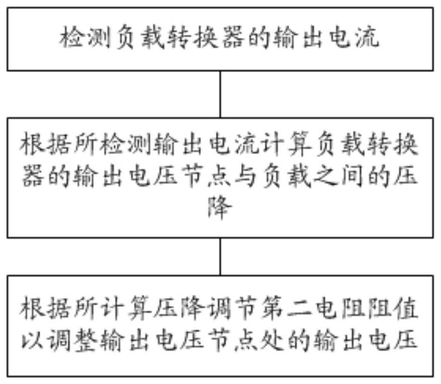
[0051] Such as image 3 As shown, based on the above embodiments, this embodiment provides a method for adjusting the output voltage of a power supply circuit, including the following steps:

[0052] S1, detecting the output current of the load converter 1;

[0053] It should be noted that the Hall sensor can be used to detect the current on the line between the output voltage node 2 of the load converter 1 and the load 4 .

[0054] Alternatively, the voltage across the output inductor of the load converter 1 is detected by a voltage sensor, and the voltage across is converted into an output current.

[0055] S2, calculating the voltage drop between the output voltage node 2 of the load converter 1 and the load 4 according to the detected output current;

[0056] It should be noted that, in this embodiment, the background software simulates the voltage drop. Specifically, the output current of the load converter 1 is transmitted to the background processing terminal 6, and ...


PUM


Abstract

The invention discloses a device and method for adjusting the output voltage of a power supply circuit. The second resistor of the feedback circuit is a resistance variable resistor. A current detector detects the output current of a load converter and transmits it to a controller; The voltage drop between the output voltage node and the load is calculated, and the resistance value of the second resistor is adjusted based on the voltage drop to adjust the output voltage at the output voltage node. The present invention predicts the voltage drop of the output voltage on the copper foil, and adjusts the feedback resistor to make up for the voltage drop of the copper foil path, and no longer pulls the feedback path to the load end, thereby reducing the disturbance of the feedback path Possibility to reduce connection space for wires.

Description

technical field [0001] The invention relates to the field of voltage adjustment, in particular to an output voltage adjustment device and method of a power supply circuit. Background technique [0002] The function of a typical power processing system is mainly divided into three parts: power converter, switch driver and controller. Others include filter circuits, feedback circuits and protection circuits. The power architecture on the motherboard of today's servers is mainly a Buck Converter (step-down converter), which consists of a controller, power converter, switch drive circuit, feedback, filtering and other circuits to form a complete power supply circuit. [0003] At present, the POL (point of load) converter load converter is used in practical applications to compare the output voltage with a single-point feedback with the reference potential inside the Buck Converter (step-down converter), and then use negative feedback to convert the POL (point of load) load)con...

Claims


Application Information

Patent Timeline
Patent Type & Authority Patents(China)
IPC IPC(8): H02M1/00H02M3/00
CPCH02M1/00H02M3/00H02M1/0009H02M1/0016H02M1/0019
Inventor 张修逢
Owner INSPUR SUZHOU INTELLIGENT TECH CO LTD
Why Eureka
Try Eureka