Road-railer two side clamping system

A technology for road-rail dual-purpose vehicles and locking pins, which is applied to rail and road dual-purpose vehicles, motor vehicles, transportation and packaging, etc. It can solve the problems of cumbersome connection steps and high precision, and achieve low precision requirements and cumbersome optimization. Action, effect of lowering altitude

Active Publication Date: 2017-05-31
XI AN RAILWAY TRANSPORTATION EQUIP
View PDF10 Cites 0 Cited by
  • Summary
  • Abstract
  • Description
  • Claims
  • Application Information

AI Technical Summary

Problems solved by technology

[0004] In view of the deficiencies in the prior art, the purpose of the present invention is to provide a new type of connection between the car body and the running device, which solves the problem of high precision and cumbersome connection steps that need to go around the car during the connection process.

Method used


Image

  • Road-railer two side clamping system
  • Road-railer two side clamping system
  • Road-railer two side clamping system

Examples


Embodiment 1

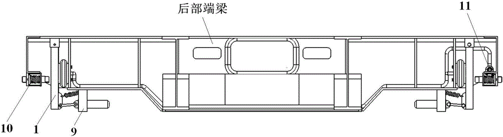
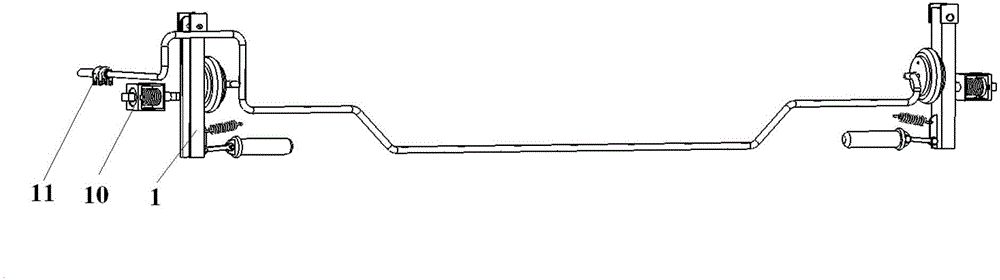
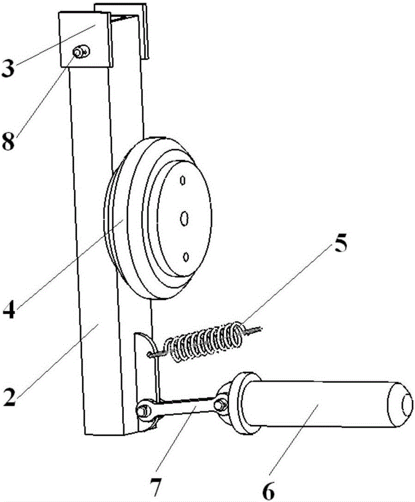
[0031] According to the above technical solution, as shown in Figure 1, the present embodiment provides a locking device 1, the locking device has a rotating shaft 2 as the main body of the rotating body, and an air spring 4, a telescopic mechanism 5, and a connecting shaft 7 are connected to the locking device. The locking pin 6 and the retractable mechanism 5 can use springs, which are simple and easy to obtain. The round pin 8 is connected to the rotating shaft 2 and the card seat 3. The card seat 3 is welded on the rear end beam of the vehicle, and the other end of the air spring 4 is passed through the bolt. Connected to the web plate of the rear end beam, the locking pin 6 is connected on the rear end beam through a guide sleeve 9, and holes on the guide sleeve 9 are connected to the rotating shaft 2 through the telescopic mechanism 5 .

[0032] The working principle of locking device 1 is:

[0033] When the compressed air inflates the air springs 4 of the two locking de...

Embodiment 2

[0038] Comply with the above technical scheme, as shown in Figure 1 to Figure 5 As shown, this embodiment provides a clamping system on both sides of a road-rail dual-purpose vehicle, which is a left-right symmetrical structural arrangement of the vehicle body, including a locking device 1, an anti-loosening device 10 and an air circuit device 11;

[0039] The anti-off device 10 includes a box body 12 with an open front and a handle 13. A horizontal positioning bar 14 is processed inside the left side of the box body 12. The handle 13 passes through both sides of the box body 12 and is positioned at the handle in the box body 12. Positioning seat 15 is installed on 13, and positioning block 16 is processed at the front end of positioning seat 15, and positioning block 16 can be embedded in the positioning bar 14 when horizontal direction, and one end of spring 17 is installed on the described positioning seat 15, the other end of spring 17 One end is fixed on the handle 13, a...

Embodiment 3

[0043]This embodiment provides a clamping system connecting the road-rail vehicle and the special railway running device, so that the road-rail vehicle can travel on the railway. The specific working process is as follows: first, connect the road-rail dual-purpose vehicle to the automobile tractor, open the valve 21 of the air circuit device 11 after connecting the air source, the air circuit device 11 is connected and supply air to the air spring 4 of the locking device 1, and the air The spring 4 is inflated to push away the rotating shaft 2, and the rotating shaft 2 pulls the connecting shaft 7, the locking shaft 6 and the telescopic mechanism 5 outward. Then, the tractor drives the public-rail vehicle to pour backward into the railway special running device 23 (the railway bogie is omitted), after pouring into the designated position, close the valve 21 of the air circuit device 11, so that the valve interface on the air spring 4 side Connected with the atmosphere to exhau...


PUM


Abstract

The invention provides a road-railer two side clamping system. The clamping system is symmetrically arranged on the two sides of a road-railer and comprises a locking device, an anti-separation device and an air channel device. The anti-separation device comprises a box body, a handle and the like, wherein the front portion of the box body is open. The air channel device transfers compressed air provided by a tractor to air springs through a pipeline. According to the road-railer two side clamping system, an operator just needs to make locking pins at the two ends of the road-railer be aligned to corresponding positions on a special railway traveling device, and operation can be completed; and compared with the prior art, the precision requirement is low, and operation is easy and convenient. Meanwhile, the air springs are reversed to serve as power components, and the tractor is sufficiently utilized for serving as an air source. Furthermore, two paths of air are controlled to be inflated and deflated simultaneously through connection of air channel pipelines and valves, the air springs on the left side and the right side of a road-railer body are driven to act simultaneously, and the complex actions of all the steps are optimized.

Description

technical field [0001] The invention belongs to the technical field of railway transportation, and in particular relates to a clamping system for both sides of a road-rail vehicle. Background technique [0002] As a new multi-purpose vehicle that can run on roads and railways, road-rail vehicles have much higher operating efficiency and economic benefits than ordinary road vehicles and ordinary railway vehicles. The appearance of the road-rail vehicle is similar to that of an ordinary semi-trailer, and it can run normally on the road through the traction of the tractor. When it is necessary to travel on the railway, a connecting device is required. [0003] The existing container-type semi-trailer connection is generally the connection between the skeleton vehicle and the container. The connection method is fixed by a four-corner turn lock. To prevent the container from jumping off, the connection is completed. Although the connection scheme of this technology can satisfy...

Claims


Application Information

Patent Timeline
Patent Type & Authority Applications(China)
IPC IPC(8): B60F1/00B60F1/04
CPCB60F1/00B60F1/046
Inventor 杜昊朱英波拜雪玲张英华
Owner XI AN RAILWAY TRANSPORTATION EQUIP
Why Eureka
Try Eureka