Internal combustion engine

a technology of combustion engine and internal combustion chamber, which is applied in the direction of engine controller, charge feed system, non-fuel substance addition to fuel, etc., can solve the problems of limiting the reduction of the detection sensitivity of line disconnection, and reducing the detection sensitivity of the pressure sensor

Active Publication Date: 2020-09-15
TOYOTA JIDOSHA KK
View PDF12 Cites 0 Cited by
  • Summary
  • Abstract
  • Description
  • Claims
  • Application Information

AI Technical Summary

Benefits of technology

[0009]With the above-described line connection portion, the sensor connection union, to which the pressure sensor is connected, is provided at a position closer to the intake connection union than the constriction. Thus, in both of a case in which the intake connection line is disconnected at the joint with the intake passage and a case in which the intake connection line is disconnected at the joint with the line connection portion, the part in which the sensor connection union is provided is exposed to the atmosphere after the intake connection line is disconnected. The detection value of the pressure sensor thus readily approaches the atmospheric pressure. That is, when the intake connection line is disconnected, the line disconnection is detected through a change in the detection value of the pressure sensor.
[0011]In the internal combustion engine of the above-described configuration, oil can enter the line connection portion when the blow-by gas that has leaked to the crankcase from the combustion chamber flows toward the intake connection line. This may cause the oil to collect on the pressure sensor, reducing the detection sensitivity of the pressure sensor.
[0012]With the above-described configuration, the sensor connection union is located vertically above the constriction even if oil enters the second space after passing through the constriction together with blow-by gas. This prevents the oil that has entered the second space from reaching the pressure sensor after passing through the sensor connection union. Accordingly, oil is prevented from collecting on the pressure sensor. That is, the above-described configuration limits reduction in the detection sensitivity of the pressure sensor and thus limits reduction in the detection sensitivity to line disconnection due to reduction in the detection sensitivity of the pressure sensor.
[0014]The above-described configuration prevents blow-by gas from directly flowing into the sensor connection line after flowing into the second space through the constriction. In other words, the blow-by gas that flows into the second space after passing through the constriction readily strikes the inner wall of the second unit. This allows oil to be separated from the blow-by gas, thereby limiting reduction in the detection sensitivity of the pressure sensor due to the flow of blow-by gas containing oil toward the pressure sensor. That is, the above-described configuration limits reduction in the detection sensitivity to line disconnection due to reduction in the detection sensitivity of the pressure sensor.
[0016]The above-described configuration prevents blow-by gas from directly flowing into the sensor connection line after flowing into the second space through the constriction. Also, the above-described configuration prevents blow-by gas from directly flowing into the intake connection line after flowing into the second space through the constriction. That is, the blow-by gas that flows into the second space after passing through the constriction readily strikes the inner wall of the second unit. Accordingly, oil is separated from the blow-by gas. This restricts the flow of blow-by gas containing oil toward the pressure sensor, thereby limiting reduction in the detection sensitivity of the pressure sensor. Further, the above-described configuration prevents the blow-by gas containing oil from being released into the intake passage.
[0018]The oil contained in the blow-by gas that has flowed into the second space strikes the wall surface of the second unit to be separated, and dribbles down to the partition plate, which constitutes the floor surface of the second space. The above-described configuration allows the oil that has dribbled down to the partition plate to flow down to the constriction under its own weight. Thus, when the operation of the internal combustion engine is stopped and inflow of blow-by gas to the second space through the constriction is stopped, the oil stored in the second space is returned to the first space, which is adjacent to the separator, through the constriction. This prevents the oil from flowing into the sensor connection line and the intake connection line. That is, the above-described configuration limits reduction in the detection sensitivity of the pressure sensor and thus limits reduction in the detection sensitivity to line disconnection due to reduction in the detection sensitivity of the pressure sensor.

Problems solved by technology

This may cause the oil to collect on the pressure sensor, reducing the detection sensitivity of the pressure sensor.
That is, the above-described configuration limits reduction in the detection sensitivity of the pressure sensor and thus limits reduction in the detection sensitivity to line disconnection due to reduction in the detection sensitivity of the pressure sensor.
This allows oil to be separated from the blow-by gas, thereby limiting reduction in the detection sensitivity of the pressure sensor due to the flow of blow-by gas containing oil toward the pressure sensor.
That is, the above-described configuration limits reduction in the detection sensitivity to line disconnection due to reduction in the detection sensitivity of the pressure sensor.
This restricts the flow of blow-by gas containing oil toward the pressure sensor, thereby limiting reduction in the detection sensitivity of the pressure sensor.
That is, the above-described configuration limits reduction in the detection sensitivity of the pressure sensor and thus limits reduction in the detection sensitivity to line disconnection due to reduction in the detection sensitivity of the pressure sensor.

Method used


Image

  • Internal combustion engine
  • Internal combustion engine
  • Internal combustion engine

Examples


Embodiment Construction

[0029]This description provides a comprehensive understanding of the methods, apparatuses, and / or systems described. Modifications and equivalents of the methods, apparatuses, and / or systems described are apparent to one of ordinary skill in the art. Sequences of operations are exemplary, and may be changed as apparent to one of ordinary skill in the art, with the exception of operations necessarily occurring in a certain order. Descriptions of functions and constructions that are well known to one of ordinary skill in the art may be omitted.

[0030]Exemplary embodiments may have different forms, and are not limited to the examples described. However, the examples described are thorough and complete, and convey the full scope of the disclosure to one of ordinary skill in the art.

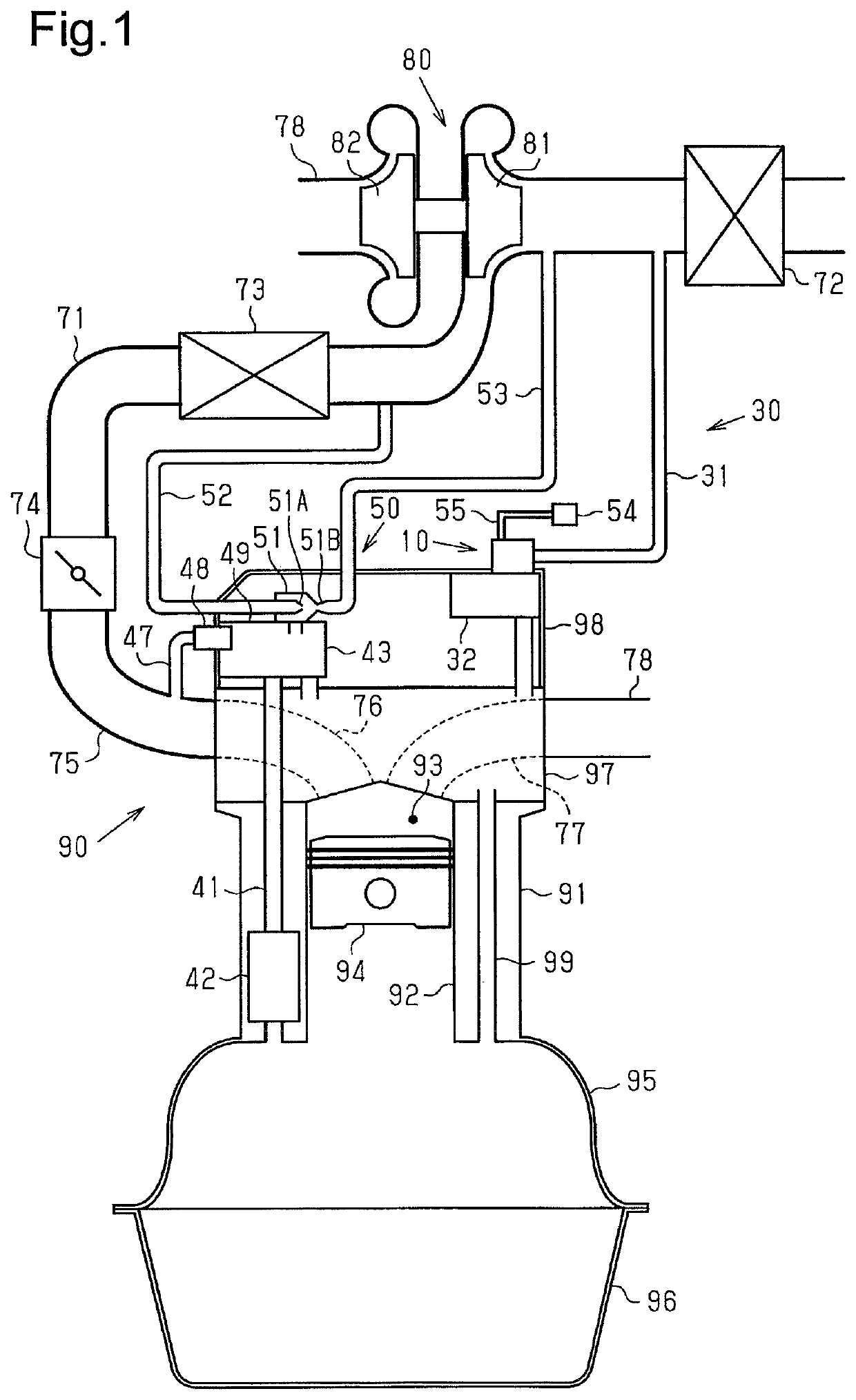
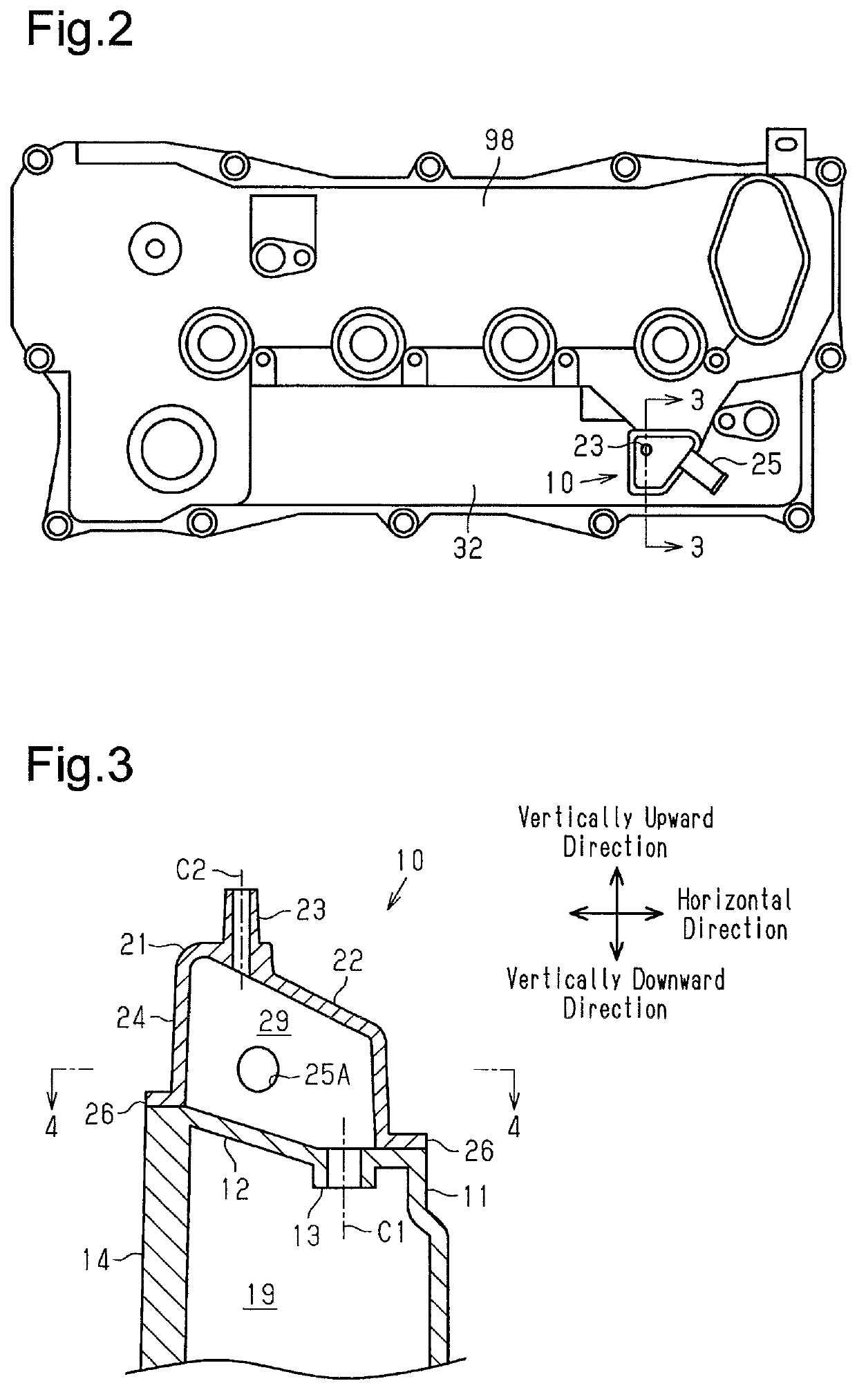
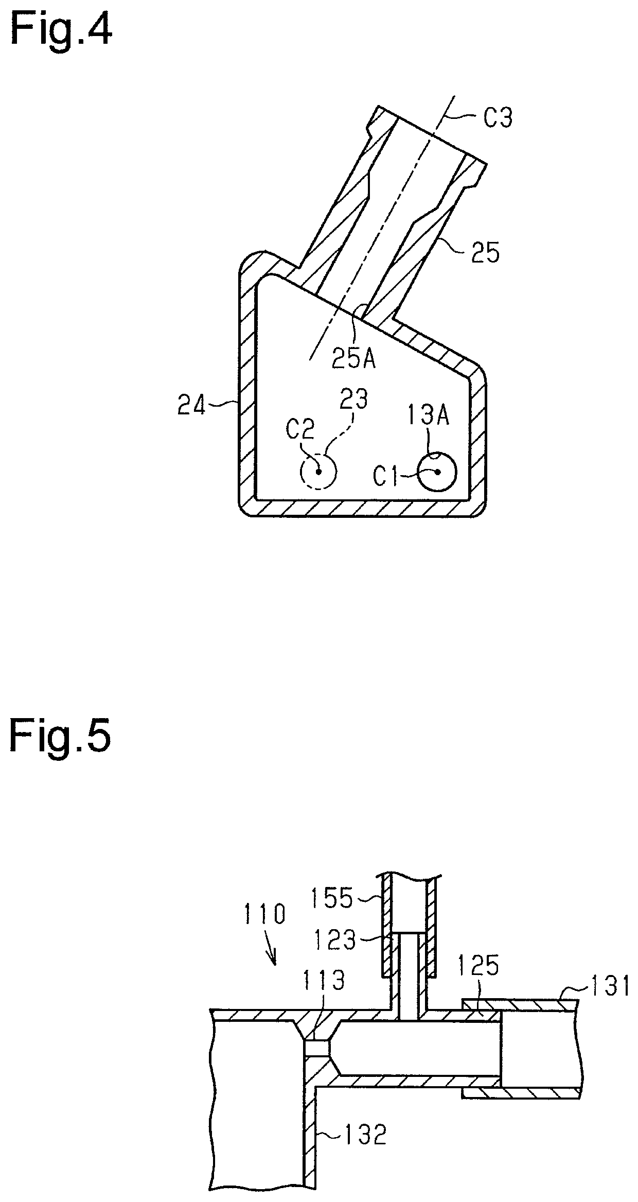
[0031]An internal combustion engine 90 according to an embodiment will now be described with reference to FIGS. 1 to 4.

[0032]FIG. 1 shows the internal combustion engine 90, which is provided with a blow-by gas...


PUM


Abstract

An internal combustion engine includes a blow-by gas treating device. The blow-by gas treating device includes a separator having a line connection portion. The line connection portion includes an intake connection union, to which an intake connection line is attached, a sensor connection union, to which a pressure sensor is connected, a partition plate, which divides the space in the separator into a first space and a second space, and a constriction, which is provided in the partition plate and allows the first space and the second space to communicate with each other. The line connection portion is constituted by combining a first unit, which includes the partition plate and defines the first space, and a second unit, which defines the second space with the partition plate of the first unit. The intake connection union and the sensor connection union are provided in the second unit.

Description

BACKGROUND1. Field[0001]The present disclosure relates to an internal combustion engine provided with a blow-by gas treating device.2. Description of Related Art[0002]Japanese Laid-Open Patent Publication No. 10-184336 discloses an internal combustion engine provided with a blow-by gas treating device. The blow-by gas treating device includes a blow-by gas passage and a communicating passage. The blow-by gas passage connects a section of the intake passage on the downstream side of the throttle valve to the head cover. The communicating passage connects a section of the intake passage on the upstream side of the throttle valve to the head cover. The internal combustion engine has a pressure sensor that detects an anomaly in the blow-by gas treating device such as line disconnection. Specifically, the pressure sensor provided in the blow-by gas passage detects the pressure in the blow-by gas passage. An anomaly is detected based on a change in the detected pressure.[0003]In a configu...

Claims


Application Information

Patent Timeline
Patent Type & Authority Patents(United States)
IPC IPC(8): F01M13/04F02M35/10F02D9/08F02M25/06
CPCF02M25/06F02M35/10209F02M35/1038F01M13/04F02D9/08F02M35/10006F02D2250/08F01M13/0405F01M2013/027F01M2013/026
Inventor ISHIKAWA, MASAMISOGAWA, KOSUKE
Owner TOYOTA JIDOSHA KK
Why Eureka
Try Eureka