Vehicle brake system

a brake system and vehicle technology, applied in the direction of brake systems, braking components, transportation and packaging, etc., can solve the problems of increased idle stroke and hunting, and achieve the effects of improving the utility of the vehicle brake system, increasing idle stroke, and high degree of utility

Active Publication Date: 2020-10-06
TOYOTA JIDOSHA KK
View PDF6 Cites 0 Cited by
  • Summary
  • Abstract
  • Description
  • Claims
  • Application Information

AI Technical Summary

Benefits of technology

[0004]In the above system in which hysteresis is provided as described above, the threshold for determining the ON state needs to be made larger than the threshold for determining the OFF state. This results in an increase in idle stroke when the braking operation is started, undesirably influencing an operation feeling in the brake operation as felt by a driver. Thus, the utility of the vehicle brake system is improved by solving the problem. An aspect of the disclosure relates to a vehicle brake system having a high degree of utility.
[0006]The vehicle brake system constructed as described above effectively prevents or reduces an occurrence of hunting and enables an operating-state determining threshold to be made comparatively small for shortening idle stroke, thereby ensuring a good operation feeling.FORMS OF THE INVENTION
[0015]The vehicle brake system of this form is characterized by the method for determining whether the brake operation member is in the operating state or in the non-operating state. In the vehicle brake system, even when the operation amount becomes less than the non-operating-state determining threshold, it is not determined that the brake operation member is in the non-operating state until a time which is not less than the first set time elapses, in order to prevent hunting. The first set time is desirably a comparatively long time, as compared with a time pitch of execution of a program, a frequency of noise of the operation amount sensor, and so on. Specifically, the first set time is about 1.0 second, for instance. There has been known a method in which a threshold for determining the operating state (operating-state determining threshold) is made larger than a threshold for determining the non-operating state (non-operating-state determining threshold) in order to prevent hunting, namely, there has been known a method in which hysteresis is provided as described above. In contrast, it is not necessary in the brake system of this form to limit a relationship in level between the operating-state determining threshold and the non-operating-state determining threshold. It is thus possible to make the operating-state determining threshold smaller than that in the system using the conventional method, resulting in shortened idle stroke in the brake operation. That is, the vehicle brake system of this form ensures improved operation feeling, as compared with the system using the conventional method.
[0020]wherein the controller shortens the first set time when the operation amount exceeds a threshold for shortening the first set time which is set to be larger than the operating-state determining threshold, and
[0032]In this form, the brake operation member is determined to be in the operating state immediately when the operation amount exceeds the second operating-state determining threshold. That is, this form prevents an occurrence of hunting and, at the same time, enables quick determination of the operating state when it is confirmed that the brake operation was made again positively or definitely by the driver.
[0038]Like the above-indicated form in which the determination of the operating state, which is to be made on the condition that the operation amount exceeds the first operating-state determining threshold, is prohibited, this form obviates the risk that the brake operation member is again determined to be in the operating state immediately after determination of the non-operating state has been made, in the situation in which the operation amount detected by the operation amount sensor fluctuates in the neighborhood of the first operating-state determining threshold. In this form, the brake operation member is determined to be in the operating state immediately when the operation amount exceeds the second operating-state determining threshold. In other words, this form prevents an occurrence of hunting and, at the same time, enables quick determination of the operating state when it is confirmed that the brake operation was made again positively or definitely by the driver.

Problems solved by technology

In this case, however, with a decrease in the thresholds, hunting tends to occur due to noise of the operation amount sensor, for instance.
This results in an increase in idle stroke when the braking operation is started, undesirably influencing an operation feeling in the brake operation as felt by a driver.

Method used


Image

  • Vehicle brake system
  • Vehicle brake system
  • Vehicle brake system

Examples


modified embodiment

[E] Modified Embodiment

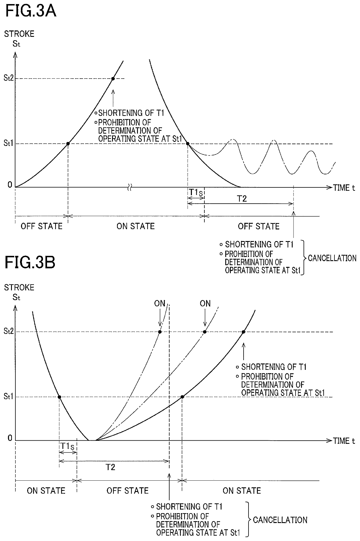
[0089]The brake system of the illustrated embodiment is configured such that, when the stroke St exceeds the second threshold St2 by which it can be determined that the brake operation was made positively or definitely by the driver, the first set time T1 is shortened, whereby it is quickly determined that the brake pedal 10 is in the OFF state when the brake operation by the driver is finished. To prevent an occurrence of hunting that may result from the configuration, the brake system of the illustrated embodiment is configured such that determination of the operating state at the first operating-state determining threshold (the first threshold St1) is prohibited and such that the prohibition of determination of the operating state at the first operating-state determining threshold is canceled when the time which is not less than the set time elapses with the stroke St kept less than the non-operating-state determining threshold (the first threshold St1).

[00...


PUM


Abstract

A vehicle brake system including: a brake operation member to be operated by a driver; a brake device configured to generate a braking force in accordance with an operation of the brake operation member; an operation amount sensor configured to detect an operation amount of the brake operation member; and a controller configured to control the braking force generated by the brake device, wherein the controller determines whether the brake operation member is in an operating state or in a non-operating state and controls, based on the determination, the braking force, and wherein the controller determines that the brake operation member is in the operating state when the operation amount exceeds an operating-state determining threshold and determines that the brake operation member is in the non-operating state when a time not less than a first set time elapses with the operation amount kept less than a non-operating-state determining threshold.

Description

CROSS REFERENCE TO RELATED APPLICATION[0001]The present application claims priority from Japanese Patent Application No. 2016-180149, which was filed on Sep. 15, 2016, the disclosure of which is herein incorporated by reference in its entirety.BACKGROUNDTechnical Field[0002]The following disclosure relates to a vehicle brake system configured to control a braking force generated by a brake device.Description of Related Art[0003]A known vehicle brake system includes (A) a brake operation member to be operated by a driver, (B) a brake device configured to generate a braking force in accordance with an operation of the brake operation member, (C) an operation amount sensor for detecting an operation amount of the brake operation member, and (D) a controller configured to control the braking force generated by the brake device. In the known brake system, the controller has a state determining portion configured to determine whether the brake operation member is in an operating state (ON...

Claims


Application Information

Patent Timeline
Patent Type & Authority Patents(United States)
IPC IPC(8): B60T13/66B60T13/14B60T13/68B60T8/88B60T8/172B60T8/40B60T8/171B60T7/04
CPCB60T8/171B60T13/146B60T13/686B60T13/662B60T8/172B60T8/885B60T8/4081B60T7/042B60T2270/413B60T2220/04B60T7/06B60T13/168
Inventor MIYAZAKI, TETSUYA
Owner TOYOTA JIDOSHA KK
Why Eureka
Try Eureka