Single-handed clamp clip

Inactive Publication Date: 2007-08-02
WOLFCRAFT
View PDF15 Cites 14 Cited by
  • Summary
  • Abstract
  • Description
  • Claims
  • Application Information

AI Technical Summary

Benefits of technology

[0004] An advantage of the present invention can be to provide a clamping tool so as to improve the utility thereof.
[0005] In an embodiment, the present invention provides that also the second clamping jaw carrier may be displaced along the track. According to the invention a releasable return locking element is associated with the second clamping jaw carrier. The return locking elements for both clamping jaw carriers act in opposite directions, thereby enabling the clamping jaws to be moved together into a clamped position or moved apart from each other into a spread position. In an embodiment of the invention, the stepped shifting gear mechanism and/or the return locking elements have a clamping lever which may be displaced against the restoring force of a spring. Each of these clamping levers may form a clamping edge by which the clamping lever along with the track may be tilted. To this end, the track preferably passes through an aperture in the clamping lever. Two diametrically opposed edges of the aperture form the clamping edges. In an embodiment of the invention, the first clamping jaw carrier cooperates with a spring which at one end is supported on the track and at the other end is supported on the first clamping jaw carrier. The spring preferably acts in the clamping direction of the first clamping jaw carrier. The invention provides that the spring supported on the end of the track impinges on the clamping jaw carrier in the clamping direction, and the return locking element acting in the opposite direction exerts a retention force directed opposite to the spring elastic force and exceeding same. As a result of this design, a clamping jaw spring acts on the first clamping jaw carrier. When the return locking element is not actuated, it withstands the force from the clamping jaw spring, although the first clamping jaw carrier may also be displaced in the clamping direction by overcoming only the frictional force exerted by the return locking element in the clamping direction. This may be achieved, for example, by actuating the stepped shifting gear mechanism. If, on the other hand, the return locking element is placed in the released position, the first clamping jaw carrier may be displaced in both directions. The displacement in the direction opposite to the clamping direction is associated with a compression of the clamping jaw spring. The displacement in the clamping direction is brought about by relaxing the clamping jaw spring. The path of this displacement may be limited by a track stop. This design provides a simpler positioning of the clamping tool on the workpiece and the clamping jaw spring may be tightened. The clamping jaw associated with the first clamping jaw carrier may be placed in a contact position on one side of the workpiece. The second clamping jaw carrier may be displaced in the clamping direction without releasing the return locking element associated therewith, until the clamping jaw for the second clamping jaw carrier is situated just in front of the corresponding contact surface of the workpiece or has already contacted the workpiece. If the return locking element for the first clamping jaw is then released, the clamping jaw spring displaces the track until both clamping jaws are in a contacting position on the workpiece. By actuating the clamping lever associated with the stepped shifting gear mechanism one or more times, the clamping jaws may be placed in a clamped position. In an embodiment of the invention, the clamping lever of the return locking element for the first clamping jaw carrier is rigidly connected to a release handle. This release handle may project through an aperture in the hand grip. The above-referenced frictional force, which prevents displacement of the first clamping jaw carrier in the clamping direction by the clamping jaw spring, is preferably exerted by a leaf

Problems solved by technology

If the clamping tool is used resting stationarily on the top side of a workbe

Method used


Image

  • Single-handed clamp clip
  • Single-handed clamp clip
  • Single-handed clamp clip

Examples


Example

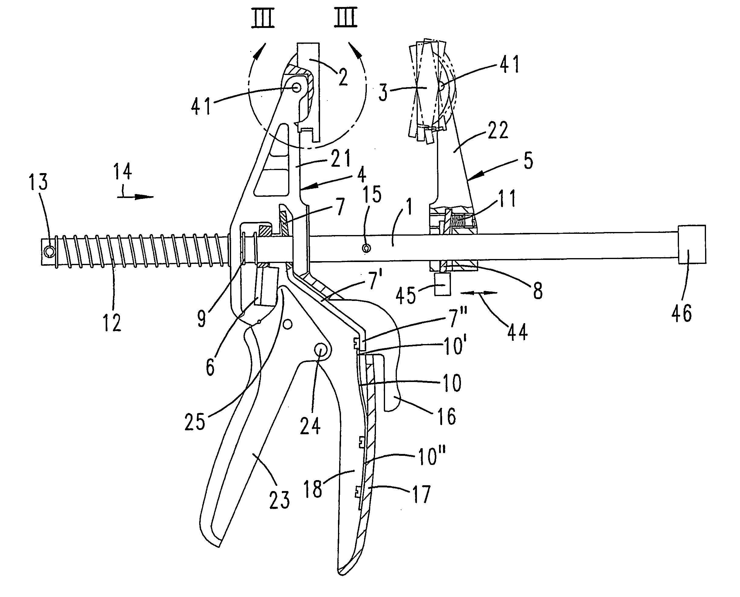
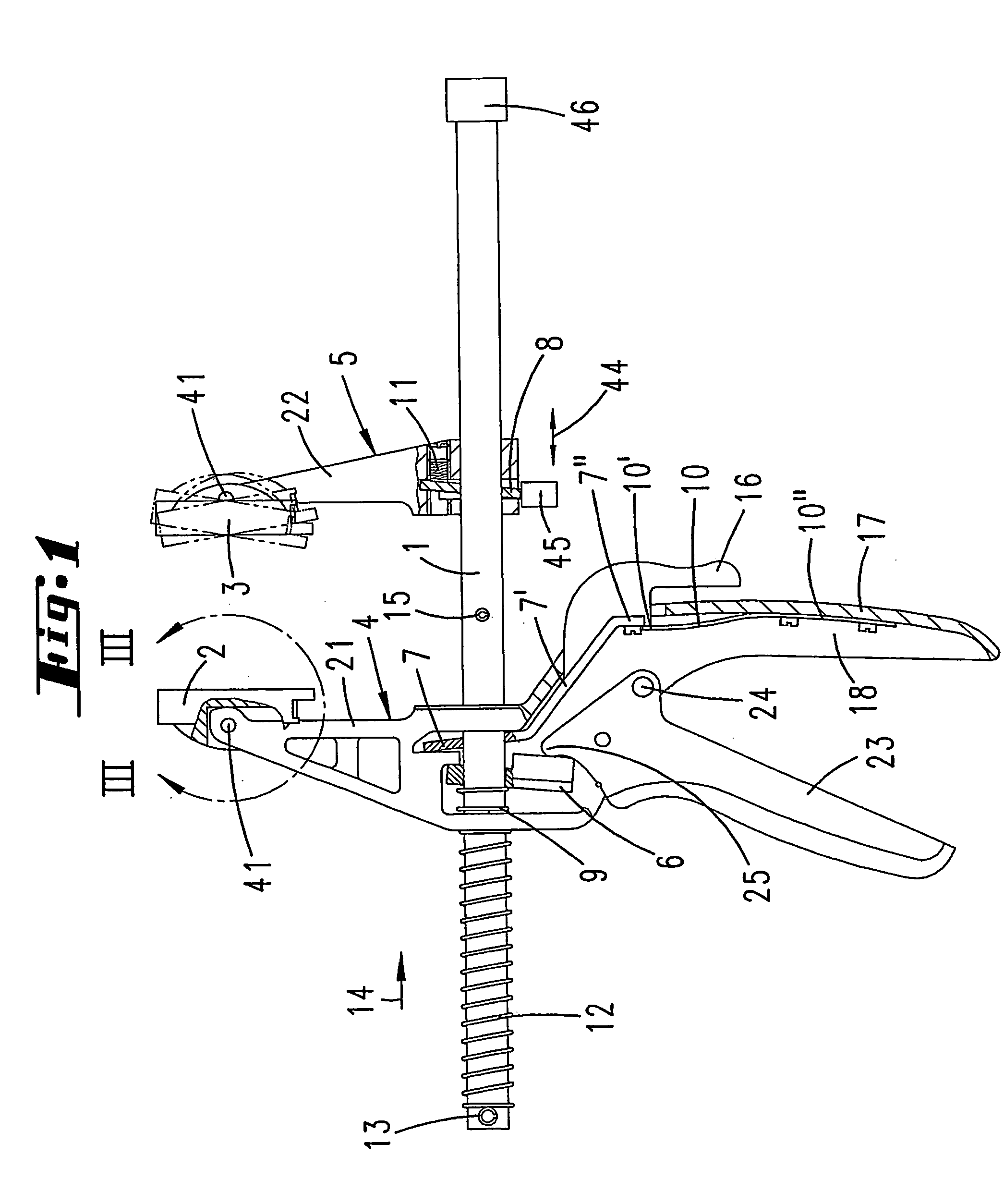
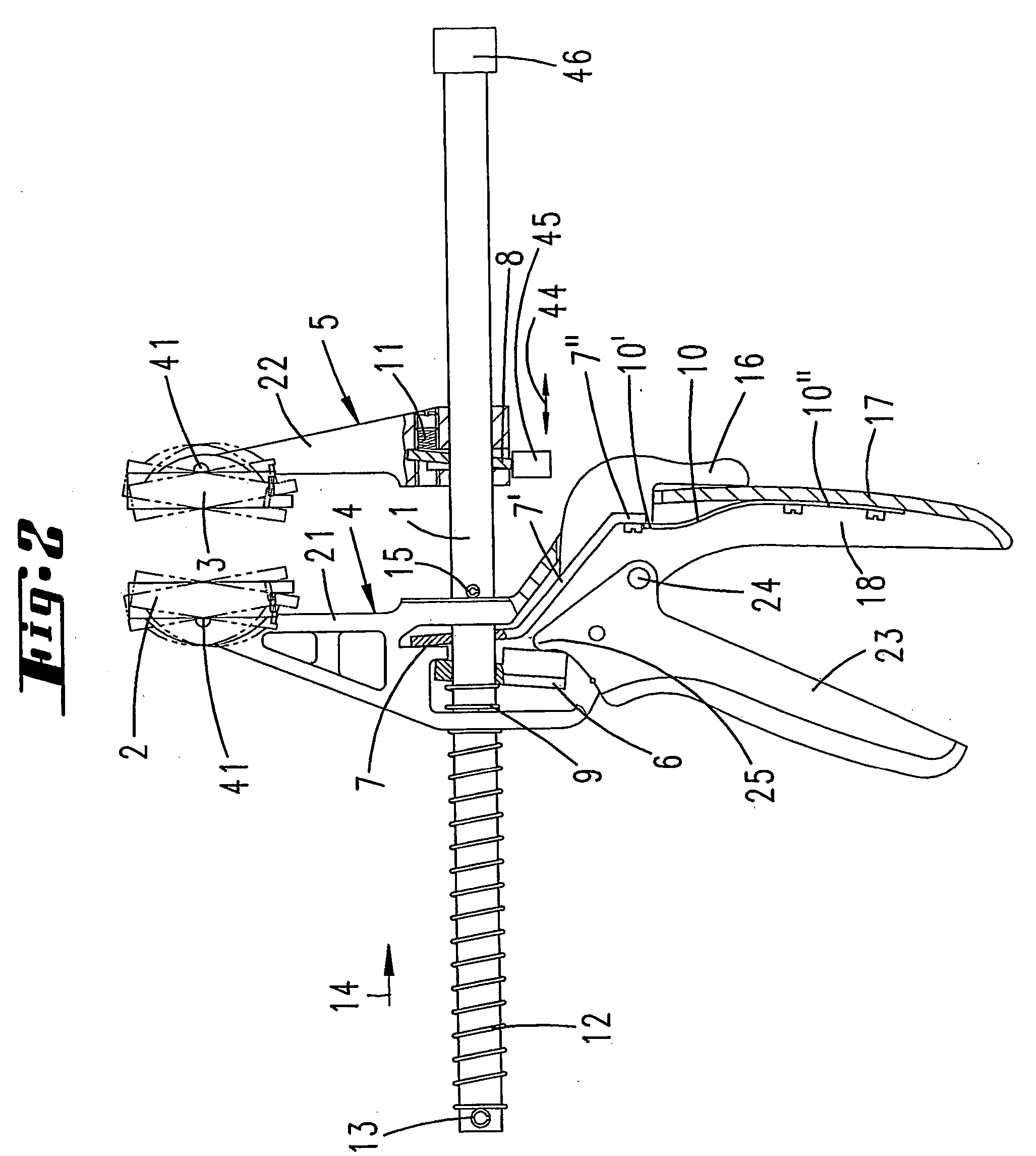
[0026] The first exemplary embodiment illustrated in FIGS. 1 through 6 is a single-handed clamping clip which has a first clamping jaw carrier 4 bearing a clamping jaw 2 which is pivotably movable on an arm 21 about an axis 41. The first clamping jaw carrier 4 can be displaced on a metal track 1 having a rectangular cross section. The clamping direction of the first clamping jaw carrier 4 is denoted by reference numeral 14. The first clamping jaw carrier 4 may be pushed or, by actuation of a stepped shifting gear mechanism, displaced in the direction 14. To this end, the operator's hand surrounds a hand grip 17 and a clamping lever 23 which extends parallel to the hand grip 17. The clamping lever 23 is able to pivot about a pivot axis 24 associated with the root of the hand grip 17. When the clamping lever 23, optionally spring-loaded by a spring (not illustrated), is pivoted, the pressure shoulder 25 is pressed against a drive lever 6.

[0027] As a result of the torque applied to th...


PUM


Abstract

A clamping tool, particularly a clamping clip, is provided with first and second clamping jaw carriers which are associated with a track and which respectively bear a clamping jaw. At least the first clamping jaw carrier can be displaced along the track in one direction by a stepped shifting gear mechanism and is prevented from being displaced in the opposite direction by a detachable return locking element and can be displaced along the track.

Description

CROSS REFERENCE TO RELATED APPLICATION [0001] This application claims priority of German Patent Application Number 102004011636.9, filed Mar. 10, 2004, and International Application Number PCT / EP2005 / 050811, filed Feb. 25, 2005, which are incorporated by reference.BACKGROUND OF THE INVENTION [0002] The invention relates to a clamping tool, in particular a clamping clip, having first and second clamping jaw carriers which are associated with a track and which respectively bear a clamping jaw, wherein at least the first clamping jaw carrier can be displaced along the track in one direction by a stepped shifting gear mechanism and is prevented from moving in the opposite direction by a releasable return locking element. [0003] A clamping tool is known from DE 197 31 579 A1, in which the first clamping jaw carrier may be displaced with respect to the track. The second clamping jaw carrier rests in a reversible but stationary manner at the end of the track. SUMMARY OF THE INVENTION [0004...

Claims


Application Information

Patent Timeline
IPC IPC(8): B25B1/00B25B5/06B25B5/16
CPCB25B5/163B25B5/068
Inventor NONIEWICZ, ZBIGNIEW
Owner WOLFCRAFT
Why Eureka
Try Eureka