
Flow control for switching

Inactive Publication Date: 2001-01-09
TELEFON AB LM ERICSSON (PUBL)
View PDF8 Cites 16 Cited by
  • Summary
  • Abstract
  • Description
  • Claims
  • Application Information

AI Technical Summary

Benefits of technology

According to the inventive concept, extremely short time intervals between the requests should be used, e.g. 3-10 cell times, so that the spreading of the traffic within the time interval will not be too big. This also means that one avoids the use of "shaping", which contributes to a lower degree of utilization of the switch. This together with the above actions means that considerably smaller output buffers can be used. The invention also permits a high degree of utilization of the switch thanks to the use of output buffers. It also permits a minimization of the size of the output buffers thanks to the short time intervals between each request from the inputs and to reference being taken to the supervision of the degree of fullness of the output buffers.

Problems solved by technology

ATM-connections where the traffic is sent with a strong "burst-like" character require large buffers which are both expensive and difficult to implement.
This structure has the best performance but is expensive and difficult to implement since large buffers are required.
As ATM-switches work with a data speed per link of up to 622 megabits per second and a total capacity of 10 Gbps or more, it is extremely difficult to construct output buffers with sufficient bandwidth and memory capacity as is required for certain of the services which should be able to be supported in an ATM-switch.
The problem with this model is that a flow control is required as cells would be lost if several inputs sent simultaneously to the same output.
Another disadvantage with the same switch structure is the known head-of-the-line (HOL) problem.
The HOL-problem thus results in a bad utilization of the switch.
In this technical field a crucial factor for costs and "time to market" is whether the buffers can be made with commercial memory capsules or whether they must be comprised in large specially constructed circuits.
This requires large and expensive output buffers since the number of cells transmitted during the long time interval can vary greatly, especially with the use of ATM-cells which often have a strongly burstlike traffic distribution.
The disadvantage with this technique is, however, that one then postpones the transmission of cells which perhaps quite well could have been sent earlier during the time interval with reference taken to the total traffic intensity.
The consequence is a bad degree of exploitation of the switch.
Moreover, with burst-like traffic there will be requests for fewer cells than that which the switch core during low traffic can take care of while requests will be refused during high traffic, which contributes to a bad degree of utilization of the switch.
It must be considered to be a problem to be able to keep a high degree of utilization of the switch in the so-called "Credit based scheme".
It must also be considered to be a problem to maintain a high security against "cell loss" without large and expensive output buffers.
Another problem is also how to be able to have small output buffers without "shaping".
A request to transmit too many cells (over-allocation) means that the input ports here request to be able to transmit so many cells that, with a switch architecture without output buffers, it would have led to the formation of a queue at the outputs and thereby lost cells if there were no output buffer.

Method used


Image

  • Flow control for switching
  • Flow control for switching
  • Flow control for switching

Examples


Embodiment Construction

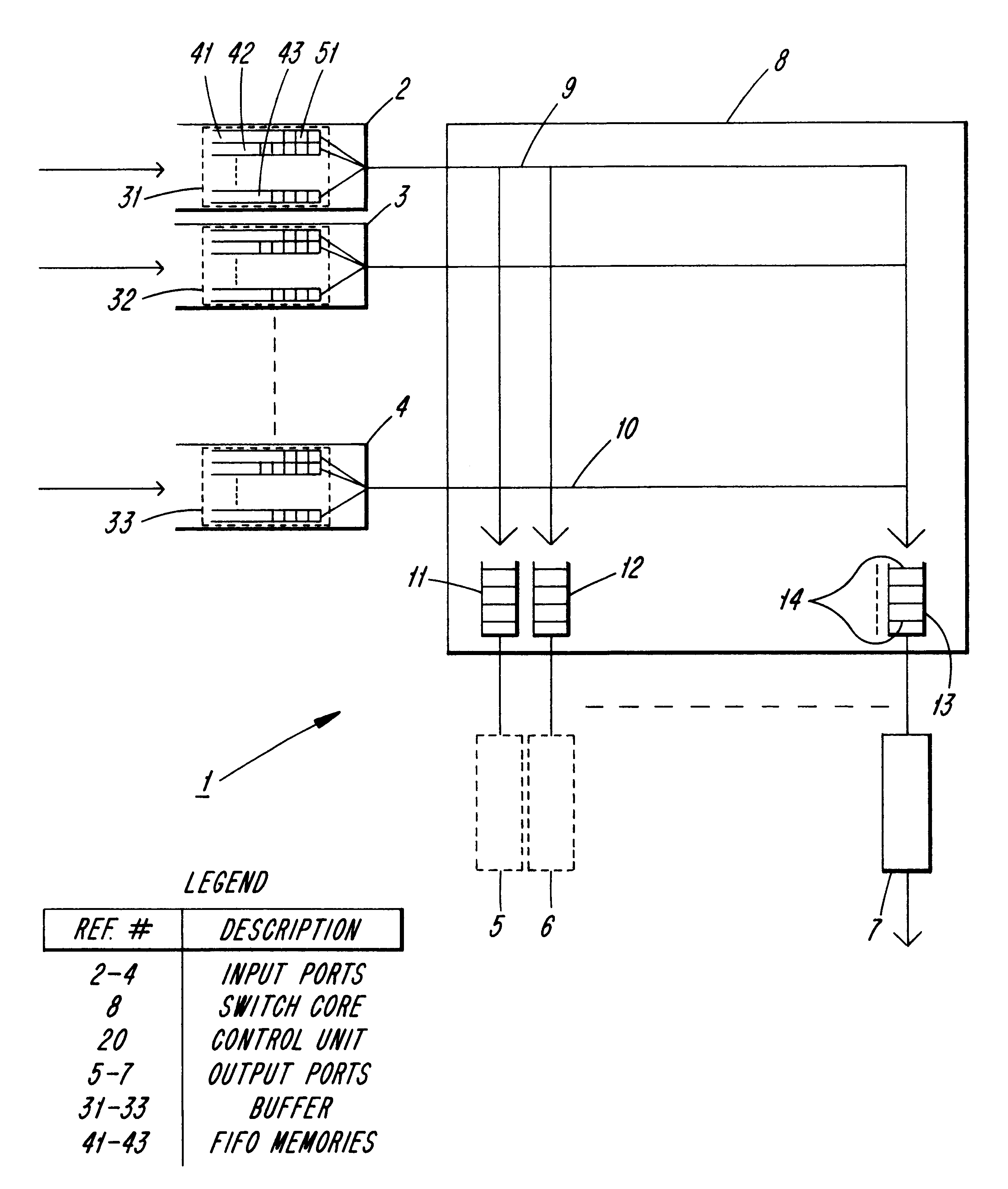
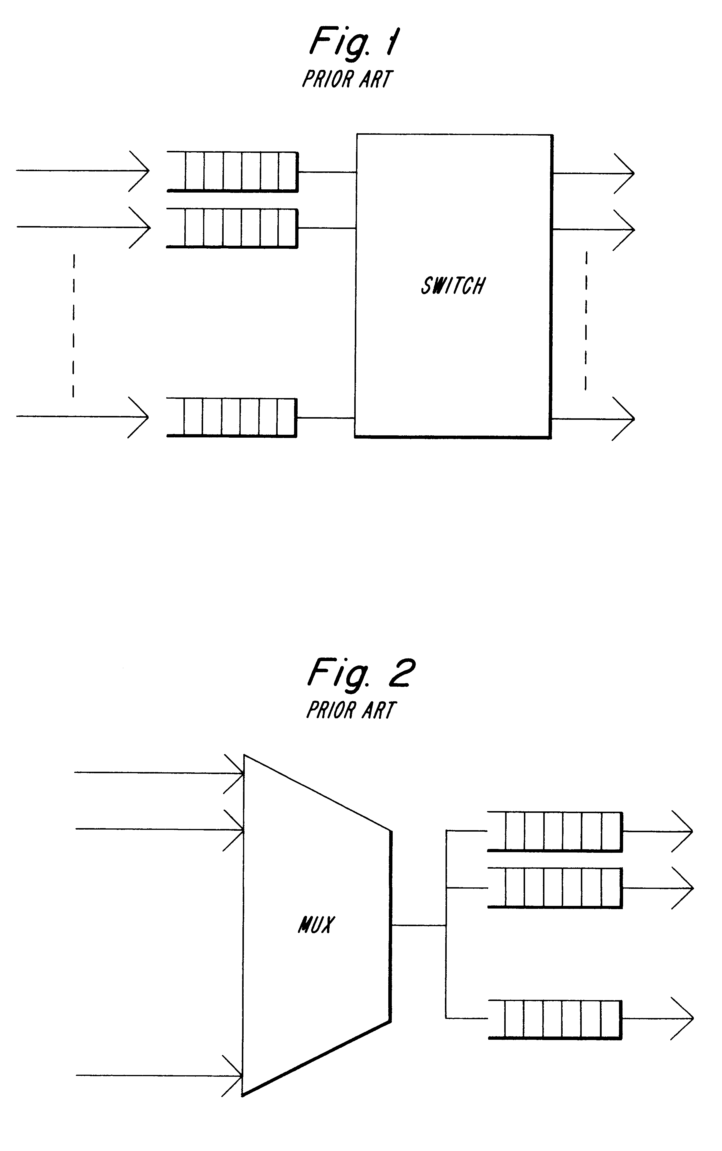
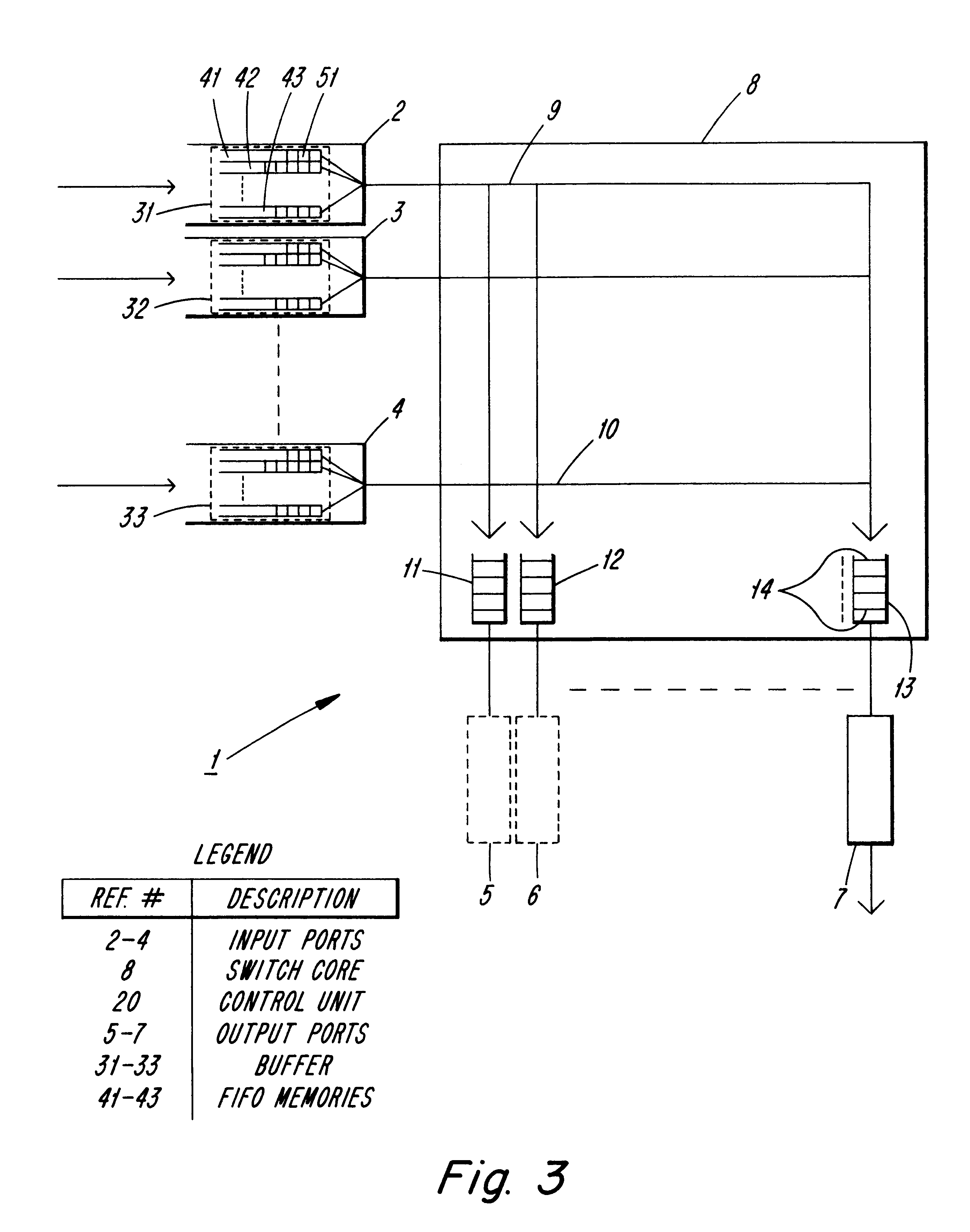
FIG. 1 shows the prior art with the buffers on the input according to a common way of building switches, and FIG. 2 shows another type with buffers on the output. A third type of switch has, according to the prior art, buffers on both the inputs and outputs and it is this type to which the invention is applicable. FIG. 3 shows the invention according to a preferred embodiment. The Figure concentrates on showing the paths for the cells through the switch 1 and, for the sake of simplicity, shows only three input ports 2-4. Furthermore, for the same reason, only three output ports 5-7 are shown. It must, however, be understood that switches of today have an extremely large number of inputs and outputs, respectively.

As FIG. 3 shows, the switch comprises a switch core 8 which in itself comprises a number of connection points (e.g. 9 and 10) in matrix form so that all inputs can reach all outputs. At each output there is an output buffer 11-13 which collects the cells and sends them furth...


PUM


Abstract

A method and a device for, preferably in ATM-traffic and in a switch with input and output buffers and with a so-called "credit based solution" for flow control, using a very short time interval between the requests from the input ports to send cells through the switch core to the output ports and where the degree of fullness of the output buffers is accurately supervised and taken into the calculations together with the number of cells in the input buffers when determined how many cells should be allowed to be sent to each output port during the next time interval. A certain over-allocation of cells to each output port is permitted.

Description

The invention relates to a method and a device, in preferably an ATM-switch which manages data communication and telephone traffic, in order to be able to have in readiness a large capacity even with relatively small and inexpensive buffers.DESCRIPTION OF RELATED ARTIn modern telecommunication systems, information is grouped into small data units called "packets" where each such packet comprises a field with a "head" which is used in order to identify the packet and a field containing useful information. A packet can also contain a field with information about where the cell originally came from. The packet is guided normally through the communication system from a source to a destination through switches intended for such packet switching which lead the packets through the data network in accordance with the information in the head of each packet and tables in the switches. Such switches receive a flow of data packets from a number of inputs. The head is read and the packet then is...

Claims


Application Information

Patent Timeline
IPC IPC(8): H04Q11/04H04L12/56H04Q3/00
CPCH04L47/10H04L47/29H04L47/30H04L47/39H04L49/105H04L49/254H04L49/30H04L49/3081H04L49/508H04Q11/0478H04L2012/5631H04L2012/5679H04L2012/5681
Inventor LARSSON, BERNDTBUHRGARD, MAGNUSKAMINSKI, KRZYSZTOF
Owner TELEFON AB LM ERICSSON (PUBL)
Learn More