Holding apparatus for a vehicle

a technology for holding apparatuses and vehicles, applied in vehicle components, color television details, television systems, etc., can solve the problems of collision with the environment or other road users, difficult to display such areas of view, and hardly possible to capture sideward areas of view next, so as to achieve quick and reliable identification

Active Publication Date: 2020-10-06
MEKRA LANG GMBH & CO KG
View PDF39 Cites 0 Cited by
  • Summary
  • Abstract
  • Description
  • Claims
  • Application Information

AI Technical Summary

Benefits of technology

[0010]In this respect, it is an object of the invention to provide a holding apparatus for a mirror replacement system camera of a vehicle which allows the vehicle driver to identify a deviation between a fixedly defined capture area which is to be shown and an actual shown capture area.
[0013]By such a holding apparatus, the driver may quickly and reliably identify whether the holding apparatus is in the operating position or not. For instance, the holding apparatus may not be in the operating position after a collision with an obstacle in the vehicle environment or by being displaced by hand by a third party (such as illegally, if the vehicle is parked and unsupervised). Or, the holding apparatus is retracted for parking or for a car-wash plant and, thus, is outside the operating position. Then, the driver reliably realizes (e.g. with starting of the vehicle) by means of a corresponding hint (signal) that the holding apparatus is not in the operating position and can adjust the same, before he drives off.
[0014]Preferably, the position of the first element to the second element comprises an operating position in which the image capture unit captures a defined capture area. In addition, it is also conceivable that the position of the first element to the second element comprises a further position, such as a retracted / folded-in position in which the second element is completely retracted and folded-in, respectively, in view of the first element. The determination of further positions of the holding apparatus has the advantage that it is not only possible to monitor whether the operating position is met, but also whether further positions which may be legally prescribed in the road traffic are achieved (such as the retraction of the outside mirror at attachment positions smaller than or equal to two meters above the lane / road surface).
[0018]According to a preferred embodiment, the signal device is arranged in the first element and the signal transmitter is arranged in the second element. Alternatively, the signal device is arranged in the second element and the signal transmitter is arranged in the first element. The choice where the signal device and the signal transmitter are arranged is dependent on how the signal unit is constructed and where the processing unit is arranged on the holding apparatus, in order to allow a data / information transmission from the signal unit to the processing apparatus which is as simple as possible and, at the same time reliable. So, for instance, it is advantageous to arrange the signal device on the same element of the holding apparatus on which the processing unit is also located and on the first element, respectively, which is fixed as concerns its location to the vehicle such that no mechanical load is applied to the electric connection.
[0020]The bearing mechanism between the first element and the second element is preferably a rotating mechanism with a rotating axis which extends in the height direction of the vehicle in a state in which it is mounted on the vehicle. In other words, the bearing mechanism may be configured such that it allows a pivot and rotating movement between the first element and the second element, e.g. around a journal. This allows the second element to be retractable relatively to the first element and, thus, that the longitudinal extension of the holding apparatus is reduced compared to the non-retracted outstretched state.
[0028]Preferably, the holding apparatus further has a processing unit which is configured to process the image data of the image capture unit. Further, the processing unit may also be configured to process the information of the signal device. Further, the processing unit may also be configured to control the signal unit and / or the image capture unit which has the advantage that the number of components which are necessary for the operation of the holding apparatus may be reduced. Alternatively, a further processing unit may also be provided which is configured to process the information of the signal device. An existing control unit (electronic control unit, ECU) of the vehicle, an ECU in the monitor, an ECU in the capture unit or an additional ECU may serve as a processing unit.

Problems solved by technology

If a camera is attached to the vehicle in such a manner, however, it is hardly possible to capture sideward areas of view next to the vehicle having similar angles of view which would be available to the driver viewing in a common side mirror without using image capture units with a comparatively large wide angle.
It is difficult to display such areas of view with camera systems which are directly attached to the vehicle.
This means that the attachment of the image capture unit, if so, is not or only poorly visible by a driver during particular driving maneuvers and, thus, in particular in the case if the attachment location of the camera sticks widely from the vehicle and, accordingly, is not congruent with the common contours of the vehicle, has the risk of a collision with the environment or other road users.
Thus, he might recognize possible risky situations which are captured only poorly or are not captured at all due to the deviation between the capture areas to be shown and the actual shown capture areas, to late or not at all which results in an increased collision risk of the vehicle with other road users or objects in the vehicle environment.

Method used


Image

  • Holding apparatus for a vehicle
  • Holding apparatus for a vehicle
  • Holding apparatus for a vehicle

Examples


Embodiment Construction

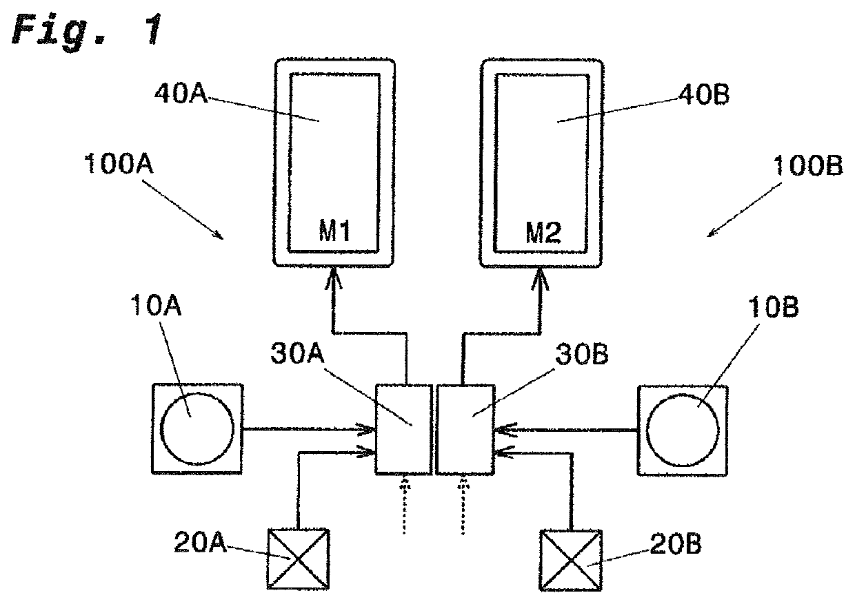
[0052]FIG. 1 shows a schematic view of two camera monitor systems 100A, 100B of a vehicle, in particular a commercial vehicle. The camera monitor system 100A may be mounted on the left side of a vehicle body, the camera monitor system 100A may be mounted on a right side of a vehicle body. Each camera monitor system 100A, 100B has an image capture unit 10A, 10B, a signal unit 20A, 20B, a processing unit 30A, 30B and a reproduction unit 40A, 40B. The image capture unit 10A, 10B is configured to capture image data of an environment around the vehicle on either a left or a right side and to supply these image data to the respective processing unit 30A, 30B. The signal unit 20A, 20B is configured to generate signals and to supply these signals to the respective processing unit 30A, 30B. It is conceivable to connect further assemblies to the processing unit 30A, 30B which supply further input parameters to the respective processing unit 30A, 30B (see dashed arrow inFIG. 1). The processing...


PUM


Abstract

A holding apparatus (50) for a vehicle has a first element (51) attachable to the vehicle (1), a second element (52) movably connected with the first element (51) via a bearing mechanism, an image capture unit (10, 10A, 10B) attached to the second element (52) and configured to capture a capture area around the vehicle (1), and a signal unit (20) configured to detect the position of the first element (51) relative to the second element (52). The signal unit (20) has a signal device (22) adapted to output a signal (S) and a signal transmitter (21) configured to operate the signal device (22) dependent on a position of the first element (51) to the second element (52) such that it outputs a signal (S).

Description

BACKGROUND OF THE INVENTION1. Field of the Invention[0001]The present invention relates to a holding apparatus for a vehicle, in particular a holding apparatus for a camera for use at commercial vehicles, and a camera monitor system with such a holding apparatus.2. Description of the Related Art[0002]With respect to automobiles, so-called fields of view are legally prescribed dependent on the type of the automobile, such as motorcycles, vehicles for passenger transport, vehicles for transport of goods, etc., which fields of view have to be depicted by a device for indirect view and which fields of view have to be visible at any time for a driver sitting on a driver's seat by means of the device for indirect view. Usually, the devices for indirect view are constituted by mirrors.[0003]In recent times, such devices for indirect view are more and more replaced and / or added by cameras and image capture units, respectively, which are configured such that a camera attached to the outside ...

Claims


Application Information

Patent Timeline
Patent Type & Authority Patents(United States)
IPC IPC(8): B60R11/04B60R1/076H04N5/225B60R1/00B60R11/00
CPCH04N5/2253B60R1/076B60R11/04B60R1/00H04N5/22525B60R2300/8046B60R2011/004B60R2011/0082H04N23/54H04N23/53
Inventor LANG, WERNERWOTSCHAL, ALEXANDERCENTMAYER, STEFAN
Owner MEKRA LANG GMBH & CO KG
Why Eureka
Try Eureka