Dual-column office table

a desk and office technology, applied in the field of desks, can solve the problems of mismatched, unattractive, complicated assembly work, etc., and achieve the effect of smooth lifting operation

Active Publication Date: 2020-10-20
JIANGYIN KAO YI MECHANIZATION IND CO LTD
View PDF22 Cites 4 Cited by
  • Summary
  • Abstract
  • Description
  • Claims
  • Application Information

AI Technical Summary

Benefits of technology

[0006]In view of the technical problem of the prior art, the primary object of the present invention is to provide a dual-column office table that can be kept vertical and stable without any tilt and is artistic.
[0013]Compared with the prior art, the present invention preferably has the following advantages:
[0014]1. The connecting rod is transversely connected between the two stationary upright columns, so that the two guiding columns can be kept vertical and stable without causing any tilt.
[0016]3. The sliding friction between the two stationary upright columns and the two guiding columns is changed to a rolling friction through the steel ball sleeves, so that the contact can be muted while sliding, and the lifting operation is smoother.

Problems solved by technology

Due to the limited height of use, its practicality is reduced greatly, and it is not ergonomic.
However, in the lifting device of the above patent, the outer peripheral surface of each support rod is sleeved with the plurality of collars, and the plurality of balls are movably mounted on the collars, therefore, the assembly work is complicated and time consuming.
Especially, an elliptical table top is to cooperate with a cylindrical movable tube, which is not only mismatched but also unattractive.
However, after the table is used for a period of time, because only three rolling units (C) are provided on the regular hexagon movable tube (B), there is a gap between the other flat surfaces (A1) not having the rolling units (C) and the inner wall surface (B1), which may lead to the looseness of the table.
The table has some disadvantages, bulky, unmatched, and unattractive.

Method used


Image

  • Dual-column office table
  • Dual-column office table
  • Dual-column office table

Examples


Embodiment Construction

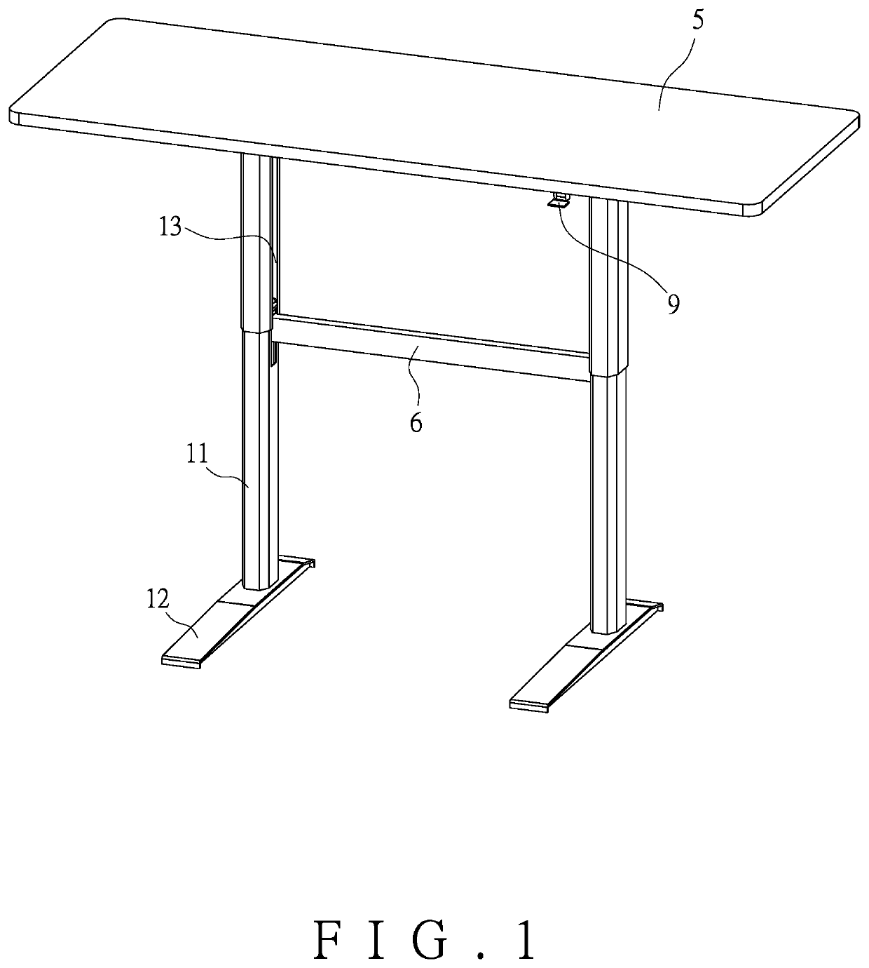
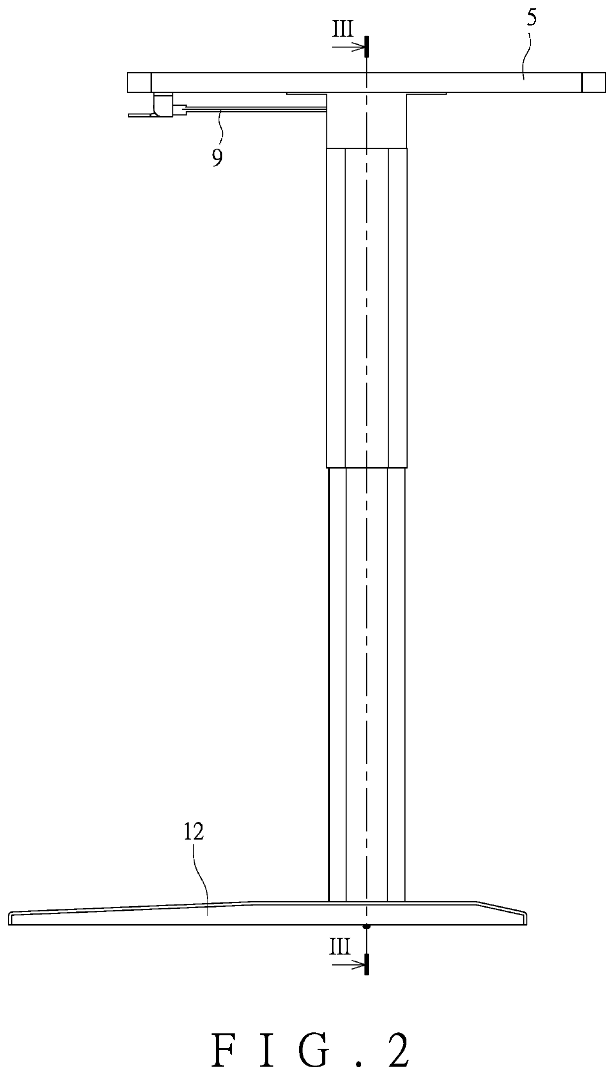
[0023]As shown in FIG. 1 and FIG. 5, a dual-column office table according to an embodiment of the present invention includes two stationary upright columns (1), two guiding columns (2), at least one steel ball sleeve (3), two driving units (4), and a table top (5).

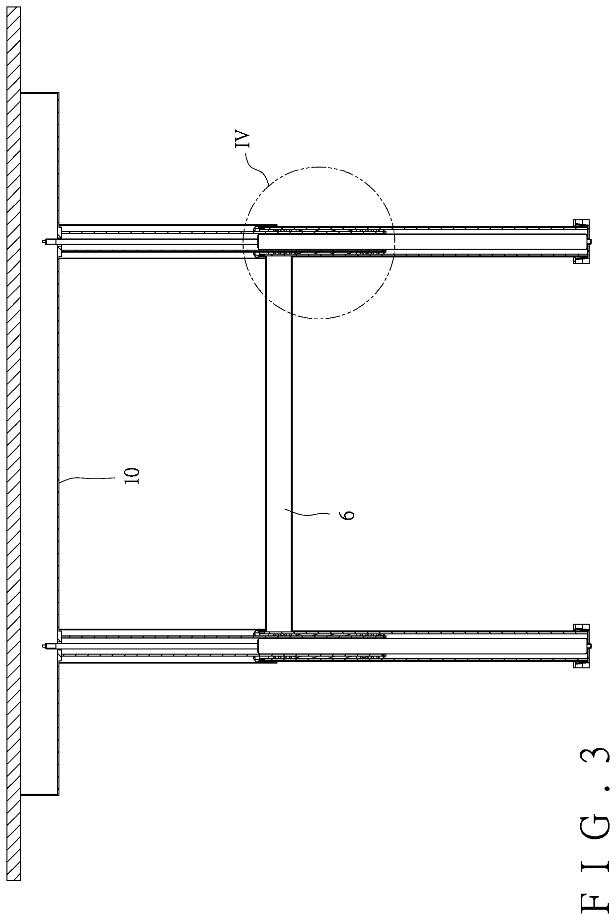
[0024]The two stationary upright columns (1) are disposed oppositely. Each of the two stationary upright columns (1) is tubular. A bottom portion of each stationary upright column (1) is provided with a respective table base (12). A connecting rod (6) is transversely connected between the two stationary upright columns (1), so that the table can be kept vertical and stable during the lifting operation without causing any tilt.

[0025]The two guiding columns (2) are disposed in the two stationary upright columns (1), separately. Top portions of the two guiding columns (2) are fixed to the table top (5). Each guiding column (2) has a circular tubular cross-section. Bottom ends of the two guiding columns (2) are free ends and c...


PUM


Abstract

A dual-column office table includes two oppositely disposed stationary upright columns with a connecting rod transversely connected therebetween, two guiding columns separately disposed in the two stationary upright columns, at least one steel ball sleeve fitted on either guiding column, two driving units separately disposed in the two guiding columns, and a table top to which a top portion of each guiding column is fixedly connected. A bottom end of each guiding column is provided with a limiting structure protruding outward. A bottom end of the each driving unit is fixed to a respective table base provided at bottom portion of each stationary upright column. The table top has a bottom surface fixedly connected with a fixing seat and is provided with a lifting control switch, the lifting control switch being connected with the driving units and having an end disposed in the fixing seat.

Description

FIELD OF THE INVENTION[0001]The present invention relates to office supplies, and more particularly to a dual-column office table that can be vertically lifted or lowered stably, and does not tilt inadvertently, and can conform to the principle of ergonomics.BACKGROUND OF THE INVENTION[0002]In general, a table has a certain height and cannot be adjusted in height. Due to the limited height of use, its practicality is reduced greatly, and it is not ergonomic. For this reason, a table with a lifting device that can be adjusted in height at will is developed, for example, Taiwanese Utility Model Patent No. M461623 titled “LIFTING DEVICE” published on Sep. 11, 2013. The lifting device comprises an upper seat, a gas pressure rod installed under the upper seat, two support rods extending downward from the upper seat, and a lower seat for receiving the gas pressure rod and the two support rods. Each of the support rods has an outer peripheral surface, at least one collar connected to the o...

Claims


Application Information

Patent Timeline
Patent Type & Authority Patents(United States)
IPC IPC(8): A47B9/20A47B9/10A47B21/02F16C3/035A47B9/04F16C29/06F16C29/04
CPCA47B9/10F16C29/069A47B21/02A47B9/20A47B9/04F16C3/035F16C29/046A47B2200/0051F16C2314/70A47B13/02A47B91/02
Inventor LIN, YEN-CHUN
Owner JIANGYIN KAO YI MECHANIZATION IND CO LTD
Why Eureka
Try Eureka