Filter press filter plate handle with braking function and braking method thereof

A filter press filter plate and handle technology, which is applied in separation methods, chemical instruments and methods, filtration and separation, etc., can solve problems such as affecting work efficiency, inability to achieve braking, and filter plate dumping, etc., to improve work efficiency and structure. Novel design to ensure the effect of safe production

Active Publication Date: 2013-01-09
杭州兴源环保设备有限公司
View PDF1 Cites 1 Cited by
  • Summary
  • Abstract
  • Description
  • Claims
  • Application Information

AI Technical Summary

Problems solved by technology

Disadvantages: First, the brake cannot be realized between the roller surface and the curved guide rail; second, the verticality of the filter plate cannot be stabilized. If you don’t pay attention, the front and rear of the filter plate will fall, which will not only affect the work efficiency, but also affect the efficiency of the filter plate. Safety

Method used


Image

  • Filter press filter plate handle with braking function and braking method thereof

Examples


Embodiment 1

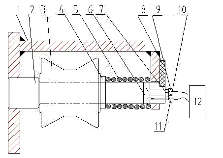
[0009] Embodiment 1: with reference to attached figure 1 . A filter plate handle of a filter press with a braking function, which includes a handle-type roller frame 1, and the trapezoidal groove-type metal roller 3 is located in the roller frame 1 through the electromagnetic roller shaft 2 below the handle-type roller frame 1, and the electromagnetic roller Axis 2 takes power through the conductive strip, and the power supply terminal of the conductive strip is connected to the power controller.

[0010] Described electromagnetic roller shaft 2 is made of positioning shaft and roller shaft, and the diameter of positioning shaft is larger than the diameter of roller shaft, and purpose is used for the limit of metal roller 3.

[0011] One end of the electromagnetic roller shaft 2 has a three-way wire channel 6, the coil 5 is wound on the roller shaft 2 and is located on one side of the metal roller 3, and the two ends of the coil 5 are respectively connected to the two power c...

Embodiment 2

[0015] Embodiment 2: On the basis of Embodiment 1, a method for braking the filter plate handle of a filter press with a braking function, the metal roller 3 wheel surfaces in the handle on both sides of the filter plate are located on the main beam guide rail, when When the power controller 12 instructs the filter plate to move, the two conductive strips 9 and 11 are non-conductive. The electromagnetic roller shaft 2 is energized to generate magnetic force and attract the metal roller 3 so that it cannot rotate, thereby achieving the purpose of braking the filter plate. The magnitude of the suction force of the electromagnetic roller shaft 2 is controlled by the magnitude of the coil current.


PUM


Abstract

The invention relates to a filter press filter plate handle with a braking function and a braking method thereof. The filter press filter plate handle with the braking function can brake a filter plate of a filter press. The wheel surfaces, which are positioned on both sides of the filter plate, of a metal roller in the handle are positioned on a guide rail of a main beam; when a power supply controller instructs the filter plate to move, two conductive bars do not conduct electricity; and when the power supply controller instructs the filter plate to stop moving, the power supply controller instructs the two conductive bars to be electrified by surrounding an electromagnetic roller shaft until a magnetic force is produced and attracts the metal roller to ensure that the metal roller fails to rotate, so that the aim of braking the filter plate is fulfilled. The filter plate handle has the advantages that: firstly, the filter plate handle brakes the filter plate for the first time, ensures that the verticality of the filter plate is steady, avoids the phenomena of forward and backward tilting of the filter plate, improves work efficiency, and ensures safety production; and secondly, the filter plate handle is novel, unique, simple, reliable and pragmatic in structural design.

Description

technical field [0001] The invention relates to a filter plate handle of a filter press capable of braking the filter plate of a filter press and a braking method thereof, belonging to the field of filter plate handle manufacturing. Background technique [0002] The founder of the applicant owns the authorized announcement number CN2503965Y, and the name is "new frame main beam and filter plate handle of filter press". The shaped wheel surface roller is located in the groove at the lower end of the handle on both sides of the filter plate and coincides with the curved beam surface of the main beam guide rail of the frame. The curved wheel surface roller located in the groove of the handle on one side of the filter plate is the reference wheel, The curved wheel surface roller in the handle groove on the other side is a free adjustment wheel. Advantages: It can effectively avoid the generation of lateral force when many filter plates are pressed together, reduce the lateral f...

Claims


Application Information

Patent Timeline
Patent Type & Authority Patents(China)
IPC IPC(8): B01D25/12
Inventor 徐孝雅周立武
Owner 杭州兴源环保设备有限公司
Why Eureka
Try Eureka