
Respiratory apparatus

a technology of respiratory apparatus and stent, which is applied in the direction of life-saving devices, medical devices, other medical devices, etc., can solve the problems of inability to completely satisfy the solution, inhalation of gases within the remainder of the device, and invasiveness of the interface device, so as to reduce the risk of trauma to the patient.

Active Publication Date: 2020-10-20
INTERSURGICAL AG
View PDF29 Cites 1 Cited by
  • Summary
  • Abstract
  • Description
  • Claims
  • Application Information

AI Technical Summary

Benefits of technology

The present invention is a respiratory device that can deliver a higher concentration of gas to a patient's lungs. This is achieved without the need for additional devices or complex arrangements, and the device can also deliver oxygen to a patient who is not breathing. The device includes a supplementary gas inlet that increases the concentration of gas inhaled by the patient. The device is particularly useful for oxygen therapy and promotes gas exchange more effectively than simple diffusion. The supplementary gas inlet generates a low level of resistance during breathing and may also provide a small amount of positive end expiratory pressure to improve respiratory efficiency. The device is made of plastics material and may include components formed of different materials to reduce risk of trauma to the patient.

Problems solved by technology

The interface device may be invasive, i.e. extending into the airways of a patient.
A disadvantage of this arrangement is that the gases within the remainder of the device, i.e. between the proximal and distal ends, will be inhaled before any therapeutic gas is inhaled.
However, this solution is not entirely satisfactory because the catheter partially obstructs the gases passageway of the device, and may cause trauma to the patient's airways during use.
However, these arrangements are much more complex than conventional interface and airway devices, and hence costly to manufacture.
However, these arrangements are also much more complex than conventional interface and airway devices, and hence costly to manufacture.

Method used


Image

  • Respiratory apparatus
  • Respiratory apparatus
  • Respiratory apparatus

Examples


first embodiment

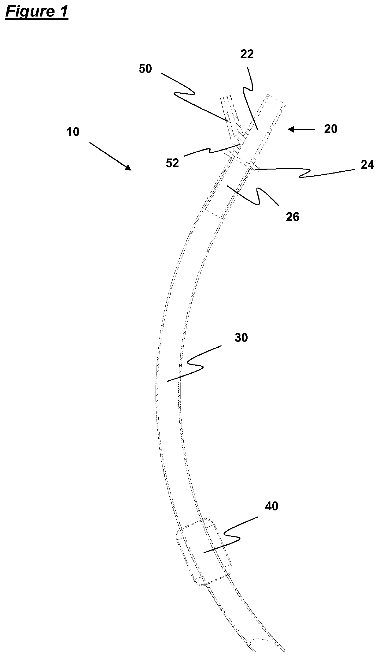
[0061]FIG. 1 shows an endotracheal tube according to the invention, which is generally designated 10. The endotracheal tube 10 comprises a connection component 20, an airway tube 30 and a sealing member 40. The endotracheal tube 10 is adapted to be inserted into the airways of a patient, through the mouth, such that the connection component 20 projects from the patient's mouth, and the sealing member 40 is accommodated within the trachea of the patient.

[0062]The airway tube 30 is a generally flexible tube, which defines a gases passageway of substantially constant circular cross-section, which is engaged with the connection component 20 at its proximal end. The sealing member 40 surrounds a portion of the airway tube 30, close to its distal end. The internal and external diameters of the airway tube 30 are chosen to correspond to the size of the patient, e.g. adult or pediatric.

[0063]The connection component 20 comprises a male tubular connector 22 suitable for connection to a conve...

second embodiment

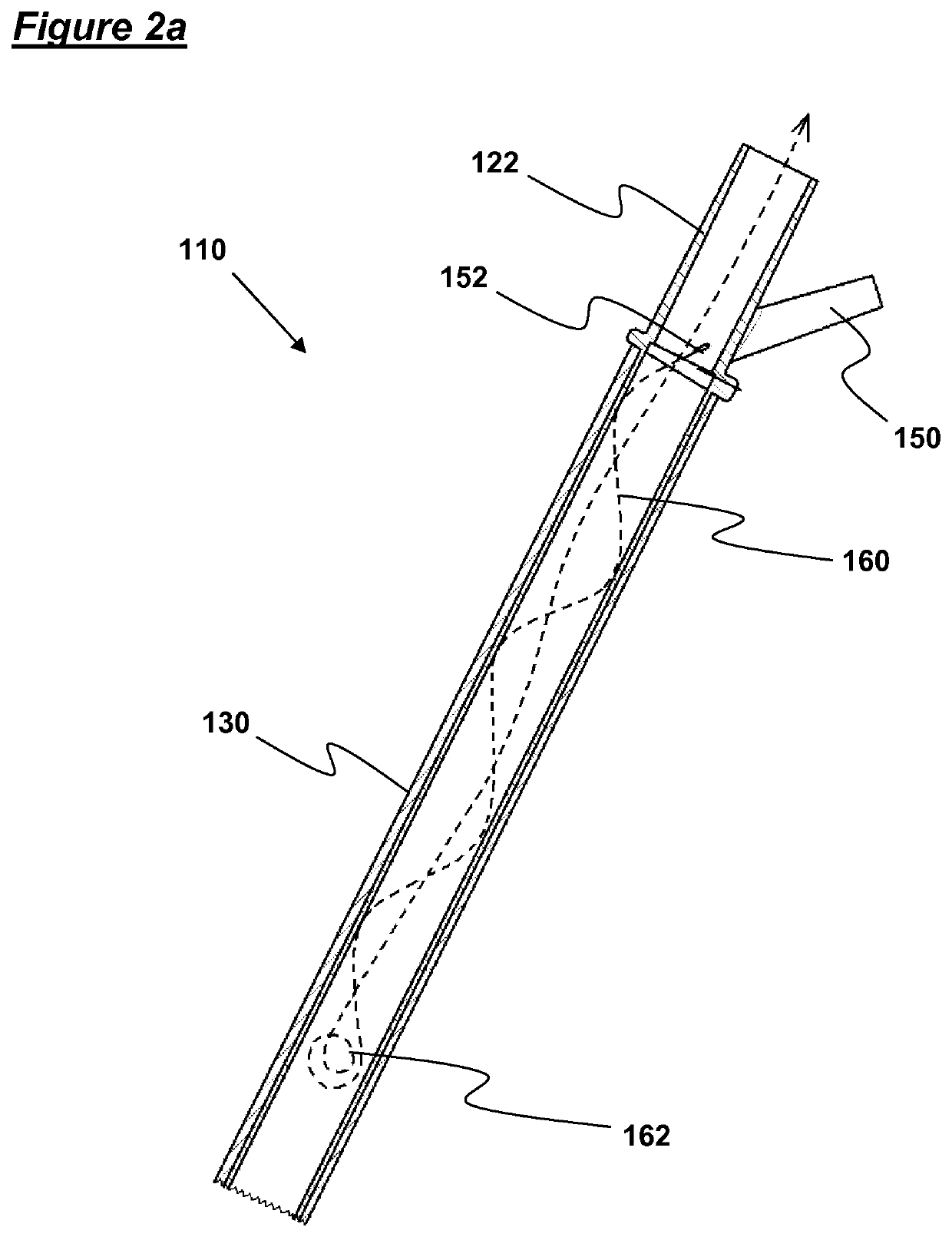
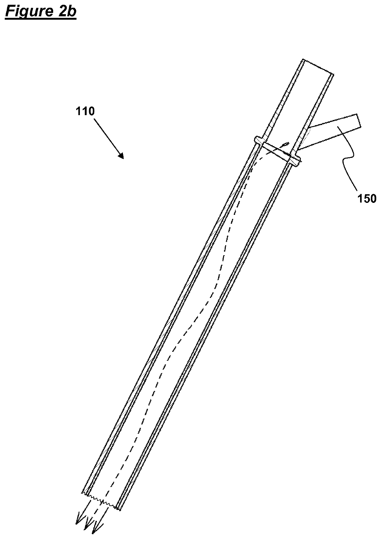
[0070]It is presently thought that the flow of oxygen, in use, in the endotracheal tube 10 occurs along the lines of that schematically illustrated in FIGS. 2a to 2c in relation to an endotracheal tube according to the invention, and described in more detail below.

[0071]FIGS. 2a to 2c show a proximal end portion of a second embodiment of an endotracheal tube according to the invention, which is generally designated 110, as well as schematic illustrations of the flow of oxygen that is thought to occur when oxygen is introduced through the oxygen inlet 150 during use.

[0072]The endotracheal tube 110 shown in FIGS. 2a to 2c comprises a connector 122 at its proximal end, and an airway tube 130 that extends into a patient's trachea during use. The connector 122 has the same form as the connector 120 described above in relation to FIG. 1. In particular, the connector includes an oxygen inlet 150. The oxygen inlet 150 is adapted to introduce a jet of oxygen into the endotracheal tube 110, s...


PUM


Abstract

A respiratory device for delivering gas to a patient comprises a gases passageway having proximal and distal ends, and a supplementary gas inlet in a side wall of the gases passageway. The supplementary gas inlet is adapted to direct gas along an interior surface of the gases passageway, such that the gas follows a generally helical path towards the distal end of the gases passageway.

Description

[0001]This application is a national stage application under 35 U.S.C. § 371 of PCT Application No. PCT / GB2011 / 050766, filed Apr. 19, 2011, which claims the priority benefit of Great Britain Patent Application No. 1006480.6, filed Apr. 19, 2010.FIELD OF THE INVENTION[0002]This invention relates to respiratory apparatus, and in particular to improvements relating to the delivery of gases to a patient.BACKGROUND OF THE INVENTION[0003]Where it is desired to deliver gas to a patient, some form of interface device is typically used. The interface device may be invasive, i.e. extending into the airways of a patient. Devices adapted for this purpose include endotracheal tubes, laryngeal mask airways and other supraglottic airways. Alternatively, the interface device may be non-invasive, i.e. not extending into the airways of a patient, examples of which include respiratory masks, nasal cannula and nasal pillows. It is also common for supplementary gas to be delivered to a patient through i...

Claims


Application Information

Patent Timeline
Patent Type & Authority Patents(United States)
IPC IPC(8): A61M16/04A61M16/12A61M16/06A61M16/08
CPCA61M16/0627A61M16/06A61M16/04A61M16/0816A61M16/12A61M2206/16A61M2202/0208A61M16/0434A61M16/0493A61M16/0409
Inventor MILLER, ANDREW
Owner INTERSURGICAL AG
Learn More