
Feeding device and portable dispensing device

a technology of a feeding device and a dispensing device, which is applied in the direction of medical devices, intravenous devices, medical devices, etc., can solve the problems of difficult to reduce (to realize compactification), the size of the entire liquid feeding device, and the slider is easily generated, so as to achieve stably and accurately feed the movable shaft, accurately feed a minute amount of liquid, and reduce the size

Active Publication Date: 2020-07-09
SEIKO INSTR INC
View PDF0 Cites 0 Cited by
  • Summary
  • Abstract
  • Description
  • Claims
  • Application Information

AI Technical Summary

Benefits of technology

The liquid feeding device of the related art has issues with rattling and instability when moving the slider due to backlash in the fitting portion between the male screw portion and the female screw portion. Additionally, the device requires a large installation space and is difficult to reduce in size. The slider is formed in a cylindrical shape, and a certain degree of diameter is required to push the reservoir plunger, which easily increases the diameter of the slider in the axial direction of the feed screw. This makes it necessary to secure a large space around the feed screw to avoid interference between the slider and the feed screw, resulting in increased dead space and decreased efficiency in space utilization.

Problems solved by technology

However, in general, backlash (gap) is generated in a fitting portion between the male screw portion and the female screw portion, and thus, rattling is easily generated in the slider due to the backlash.
Accordingly, it is difficult to stably and accurately move the slider, and thus, there is room for improvement.
Accordingly, it is difficult to reduce (to realize compactification) a size of the entire liquid feeding device.
Accordingly, a dead space increases, space efficiency deteriorates, and thus, it is difficult to decrease the size of the entire liquid feeding device.

Method used


Image

  • Feeding device and portable dispensing device
  • Feeding device and portable dispensing device
  • Feeding device and portable dispensing device

Examples


Embodiment Construction

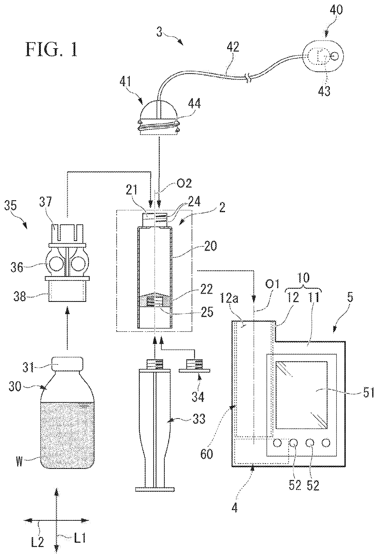
[0036]Hereinafter, embodiments of a feeding device and a portable dispensing device according to the present invention will be described with reference to the drawings. In the present embodiment, a case where the feeding device and the portable dispensing device are applied to a medicinal injection device which injects a medicinal solution into a body of a user will be described as an example.

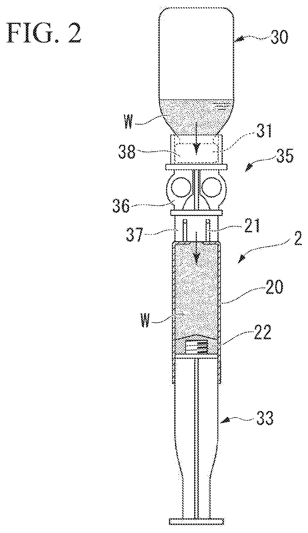
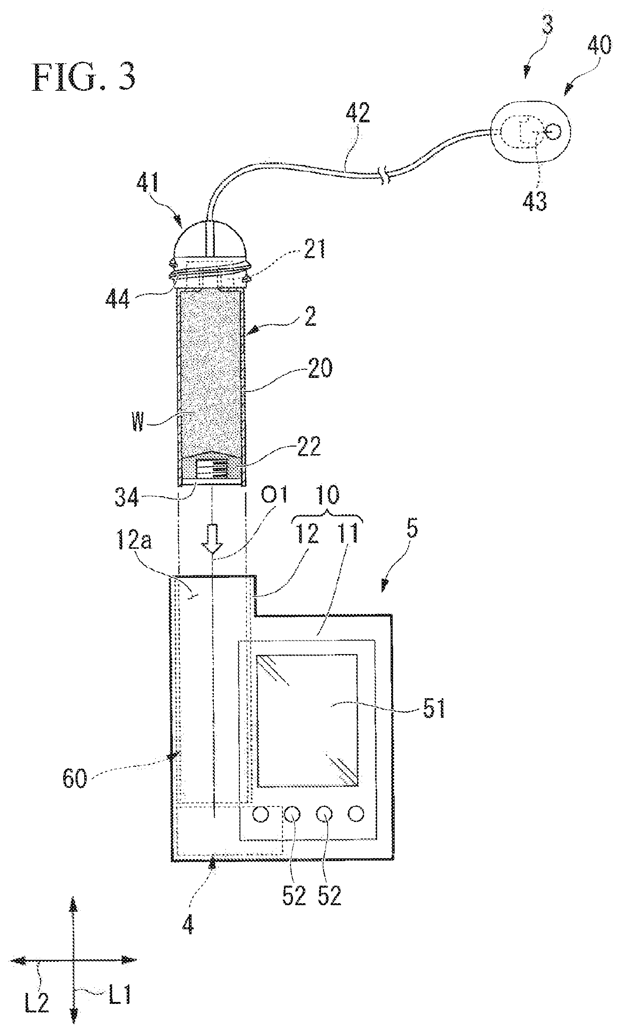
[0037]As shown in FIG. 1, a medicinal injection device l of the present embodiment includes a reservoir 2 which is filled with a medicinal solution W (content), an injection set 3 which injects the medicinal solution W dispensed from an inside of the reservoir 2 into the body of the user, and a liquid feeding device (portable dispensing device according to the present invention) 5 which includes a feeding device 4 therein, is mounted to be removable from the reservoir 2, and dispenses the medicinal solution W from the inside of the reservoir 2 using the feeding device 4. In addition, the medici...


PUM


Abstract

A feeding device according to the present invention includes a tubular body which has an a female screw portion, a movable shaft which has a male screw portion and is movable between a start position and an end position according to a rotation of the tubular body, a final gear which is provided in the tubular body, a drive unit which has the driving gear, a power transmission mechanism which transmits a driving force from the driving gear to the final gear via a plurality of intermediate gears, and a biasing mechanism which is configured to apply a biasing force to the movable shaft. At least one of the plurality of intermediate gears is a two-stage gear. The biasing mechanism is configured to apply the biasing force from the end position toward the start position and presses the male screw portion against the female screw portion to the start position side.

Description

RELATED APPLICATIONS[0001]This application claims priority to Japanese Patent Application No. 2019-001085 filed on Jan. 8, 2019, the entire content of which is incorporated herein by reference.BACKGROUND OF THE INVENTION1. Field of the Invention[0002]The present invention relates to a feeding device and a portable dispensing device.2. Description of the Related Art[0003]In the related art, for example, as described in Published Japanese Translation Nos. 2010-509984 and 2007-528260 of the PCT International Publication, as a device for feeding a liquid, a liquid feeding device is known, which feds a liquid filling a reservoir into a human body by moving a plunger by driving a gear.[0004]The liquid feeding device includes a drive motor having a drive shaft, a plurality of spur gears which are rotated according to a rotation of the drive shaft, a feed screw which is rotated by rotations of the plurality of spur gears, and a cylindrical slider which is configured to move in an axial dire...

Claims


Application Information

Patent Timeline
Patent Type & Authority Applications(United States)
IPC IPC(8): A61M5/145A61M5/142
CPCA61M5/1454A61M2205/8206A61M2205/103A61M5/14248A61M2205/50A61M5/14566A61M5/31528
Inventor ENDO, YOICHISATO, AKEHIKOOAKU, MASAMIASAI, SHINICHI
Owner SEIKO INSTR INC
Learn More