Device for fabricating annular pieces by selectively melting powder, the device including a powder wiper

a selective melting and annular piece technology, applied in the direction of additive manufacturing processes, manufacturing tools, manufacturing driving means, etc., can solve the problem of difficult to achieve uniform thickness of powder layers, and achieve the effect of reducing manual intervention, reducing labor intensity, and being more economical

Active Publication Date: 2020-10-20
SN DETUDE & DE CONSTR DE MOTEURS DAVIATION S N E C M A
View PDF9 Cites 0 Cited by
  • Summary
  • Abstract
  • Description
  • Claims
  • Application Information

AI Technical Summary

Benefits of technology

[0007]By means of the angle formed by the wiper relative to the radial direction, surplus powder is removed laterally, e.g. outwards. This makes it possible to spread the powder in uniform manner over the annular zone, and to expel the surplus powder towards the inside or the outside of the annular zone. Thus, when the wiper goes back over where it has already passed, it is ensured that there is no longer any surplus powder, such that the powder layer is not degraded by this second pass. Consequently, the “powder connection” between the beginning and the end of the azimuth stroke of the dispenser is uniform with the remainder of the annular powder layer, which layer thus presents thickness that is uniform over its entire extent.
[0029]This also makes it possible to recover in automatic manner the removed surplus powder, thereby minimizing manual interventions and consequently minimizing the risks of erroneous manipulations that might degrade the powder layer. This serves indirectly to improve uniformity and uniformity of thickness of the powder layer.

Problems solved by technology

This problem is particularly sensitive for pieces of annular shape, in particular when the powder dispenser is rotary and ends its annular path in the same place as where it began it.
That gives rise to a (connection) zone where uniformity in the thickness of the powder layer is particularly difficult to achieve.

Method used


Image

  • Device for fabricating annular pieces by selectively melting powder, the device including a powder wiper
  • Device for fabricating annular pieces by selectively melting powder, the device including a powder wiper

Examples


Embodiment Construction

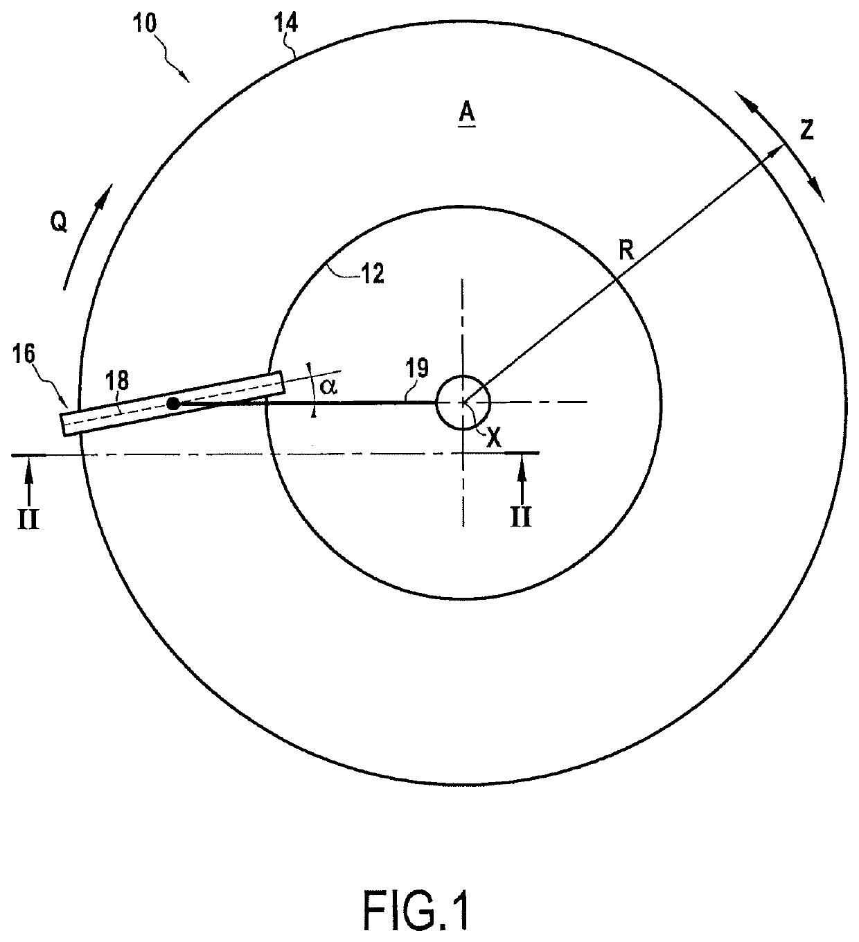
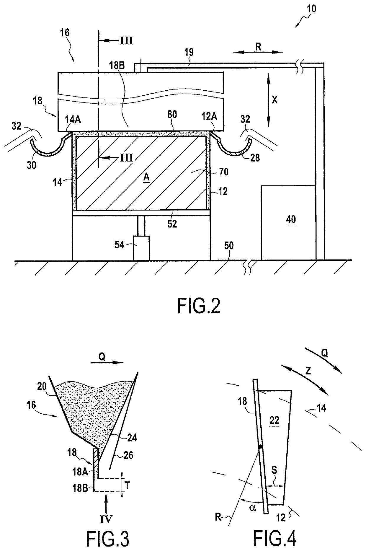
lass="d_n">[0035]FIGS. 1 and 2 show a device 10 for fabricating annular pieces by selective melting of powder. Naturally, and as a general rule, the powder is a metal powder that is sintered by one or more laser heads or by electron beam(s). There is thus alternation between depositing a layer of powder, and then selectively sintering the layer of powder by means of a laser head or an electron beam. This is known to the person skilled in the art, and is therefore not described in the present disclosure.

[0036]The device 10 has an inner annular wall 12 and an outer annular wall 14 defining an annular zone A for depositing powder. The walls 12 and 14 are concentric, having a common axis X defining an axial direction X. The radial and azimuth directions are represented respectively by arrows R and Z. As shown in FIG. 2, the walls 12 and 14 are mounted to be stationary relative to a base 50, and a tray 52 that is mounted on a support 54, that is slidable in the axial direction X, and tha...


PUM

PropertyMeasurementUnit
angleaaaaaaaaaa
angleaaaaaaaaaa
angleaaaaaaaaaa

Abstract

A device fabricates annular pieces by selectively melting powder. The device includes an inner annular wall and an outer annular wall that are concentric and that define an annular powder deposition zone, and a powder dispenser movable in rotation about an axis of the inner and outer annular walls. The powder dispenser includes a wiper extending between the inner annular wall and the outer annular wall and forming an angle with the radial direction of the inner and outer annular walls.

Description

FIELD OF THE INVENTION[0001]The invention relates to the field of fabricating pieces by selectively melting powder, and in particular to a device for fabricating annular pieces by selectively melting powder. Naturally, the term “annular piece” is used to mean any cylindrical piece that is of circular section, or frustoconical, or a body of revolution, or the equivalent.BACKGROUND OF THE INVENTION[0002]Before sintering the powder in selective manner, fabricating pieces by selectively melting powder requires a layer of powder to be deposited with thickness that is uniform (i.e. without any local extra thicknesses or shortages). The quality of the piece depends in particular on the quality of the uniformity of the thickness of the powder layer that is to be sintered. This problem is particularly sensitive for pieces of annular shape, in particular when the powder dispenser is rotary and ends its annular path in the same place as where it began it. That gives rise to a (connection) zone...

Claims


Application Information

Patent Timeline
Patent Type & Authority Patents(United States)
IPC IPC(8): B23K26/34B29C64/153B29C64/241B22F3/105B33Y30/00B23K26/70B33Y80/00B29C64/214B23K26/144B23K101/30
CPCB29C64/153B33Y80/00B29C64/241B23K26/34B23K26/144B22F3/1055B29C64/214B23K26/702B33Y30/00B23K2101/30B22F2003/1056Y02P10/25B22F3/003B22F10/00B22F12/67B22F12/53B22F10/28B22F10/73
Inventor BOUR, JEAN-LUC DENISCHANTOISEAU, OLIVIER PASCAL PAUL
Owner SN DETUDE & DE CONSTR DE MOTEURS DAVIATION S N E C M A
Why Eureka
Try Eureka