Method and apparatus for controlling the blowing air and cooling air of an I.S. glassware forming machine

a technology of glassware forming machine and blowing air, which is applied in the direction of glass blowing apparatus, glass making apparatus, glass shaping apparatus, etc., can solve the problems of low mechanical stability and low thermal conductivity of glass, and achieve the effect of minimizing the operation of the glassware forming machin

Active Publication Date: 2016-10-04
HEYE INT
View PDF16 Cites 2 Cited by
  • Summary
  • Abstract
  • Description
  • Claims
  • Application Information

AI Technical Summary

Benefits of technology

[0021]The features of still further embodiments of the apparatus are directed to a pipe section intended to introduce cooling air, a blow pipe which protrudes into the hollow glass article and can be fixed in an axially displaceable manner to the blow head. In the cooling phase, this permits effective internal cooling of the hollow glass article, in particular the lower regions thereof adjacent to a floor.
[0023]It is apparent from the statements above that by means of the inventive method or the apparatus presented, manual interventions in the operation of a glassware forming machine can be minimized.

Problems solved by technology

In this case, consideration is to be given to the low mechanical stability due to the temperature of the produced hollow glass articles during and immediately after shaping, and to the low thermal conductivity of the glass.
However, to achieve a reproducible product quality, it is necessary to produce uniform deformation conditions which is achieved only in partial aspects by this prior art.

Method used


Image

  • Method and apparatus for controlling the blowing air and cooling air of an I.S. glassware forming machine
  • Method and apparatus for controlling the blowing air and cooling air of an I.S. glassware forming machine
  • Method and apparatus for controlling the blowing air and cooling air of an I.S. glassware forming machine

Examples


Embodiment Construction

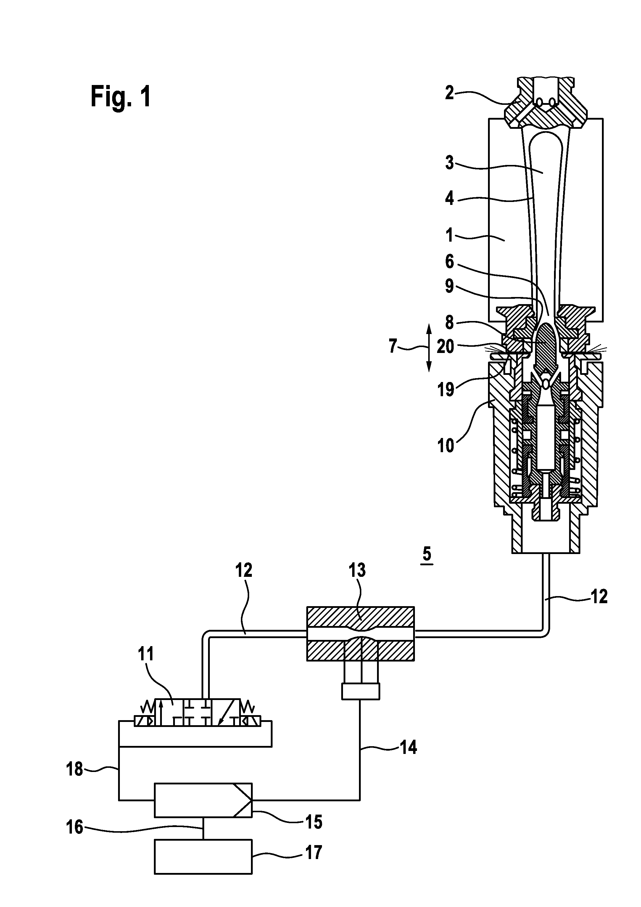
[0033]In FIG. 1, the parison mold of an I.S. glassware forming machine which is formed so as to be divided along an axial plane and consists of two mold halves is designated by the reference numeral 1 and is located in the closed position and is closed at the top side by means of a pre-floor 2. Located inside the mold space 3 after the shaping process is completed is the parison 4 whose neck opening 6 facing towards the underside 5 is confronted by a plunger 8 which is displaceable in the longitudinal direction 7.

[0034]FIG. 1 shows the plunger 8 in a position which uncovers an annular flow cross-section 9 in the region of the neck opening 6, via which cross-section blowing air can be introduced, starting from a plunger cylinder upper part 10, into the mold space 3 of the parison 4.

[0035]FIG. 1 shows the procedure of pre-blowing which is used only when the process is conducted in the manner of a blow-and-blow process which is known per se.

[0036]Blowing air is supplied to the plunger ...


PUM

PropertyMeasurementUnit
volume flow rateaaaaaaaaaa
temperatureaaaaaaaaaa
heat lossaaaaaaaaaa

Abstract

In order to achieve reproducible operating parameters of the shaping process of an I.S. glassware forming machine, a central control of all blowing and cooling air flows is proposed, in which in accordance with sections a volume flow of the cooling air including the inlet-side and outlet-side temperatures thereof are measured by means of a measuring device (51, 52) and a heat loss which is associated with the section is ascertained. The heat thus removed in sections is compared with standard values, wherein in the event that tolerance zones are exceeded a variation of the volume flow is initiated by the actuation of restrictors (53, 54). All of the sections of the glassware forming machine which are intended for passage of cooling air are monitored in this way, namely on the basis of a determinable heat loss, so that uniform cooling conditions, which are adapted to a mathematical model, and in this respect a reproducible product quality are achieved.

Description

BACKGROUND OF THE INVENTION[0001]The invention relates to a method and apparatus for controlling blowing air and / or cooling air in an I.S. glassware forming machine.[0002]Control of blowing air during the production of hollow glass articles is significant for the rate of shaping and cooling and, associated with this, for the mechanical stability of the articles in the individual stages of the production process. In this case, it is a question of achieving a reproducible article quality in the face of external, but also internal, disruptive influences caused, e.g., by wear.[0003]Patent document GB 2 297 548 A discloses a method and an apparatus for controlling the blowing pressure of a glassware forming machine, in which a line intended for supplying blowing air, a line intended for discharging blowing air and a line intended for measuring pressure issue in the blowing head which closes a blow mold at the top side. The lines used for the supply and discharge of blowing air are fitted...

Claims


Application Information

Patent Timeline
Patent Type & Authority Patents(United States)
IPC IPC(8): C03B9/36C03B9/453C03B9/40C03B9/38C03B9/193
CPCC03B9/3816C03B9/1936C03B9/3618C03B9/3627C03B9/3636C03B9/3645C03B9/3672C03B9/385C03B9/3825C03B9/3866C03B9/3875C03B9/3883C03B9/3891C03B9/403C03B9/4535C03B9/406
Inventor BORCHERDING, KARL-FRIEDRICHFELGENHAUER, BENEDIKTISENSEE, DENNISMOLLER, ECKHARD
Owner HEYE INT
Why Eureka
Try Eureka