
Self-optimizing subcooler control

a subcooler and self-optimization technology, applied in the field of climate control systems, can solve the problems of reducing the capacity of the evaporator, and reducing the efficiency of the system, so as to reduce the efficiency, the effect of reducing the return and reducing the efficiency

Active Publication Date: 2020-10-20
HEATCRAFT REFRIGERATION PRODS
View PDF5 Cites 0 Cited by
  • Summary
  • Abstract
  • Description
  • Claims
  • Application Information

AI Technical Summary

Benefits of technology

[0004]A refrigeration system may include a subcooler, which may increase capacity of the evaporator by cooling the refrigerant that leaves the condenser before the refrigerant enters the evaporator. Typically, subcoolers provide constant liquid outlet temperature throughout the year. For some loads and ambient conditions, providing a constant liquid outlet temperature may be sub-optimal. Overcooling the liquid may result in diminished returns, and thus a lack of efficiency. Furthermore, certain known refrigeration systems that include a subcooler require two expansion valves. The first expansion valve controls vapor outlet superheat while the second valve controls subcooling and the rate at which refrigerant is discharged to the evaporator to cool refrigerated cases. However, using two valves adds cost and complexity to the system.
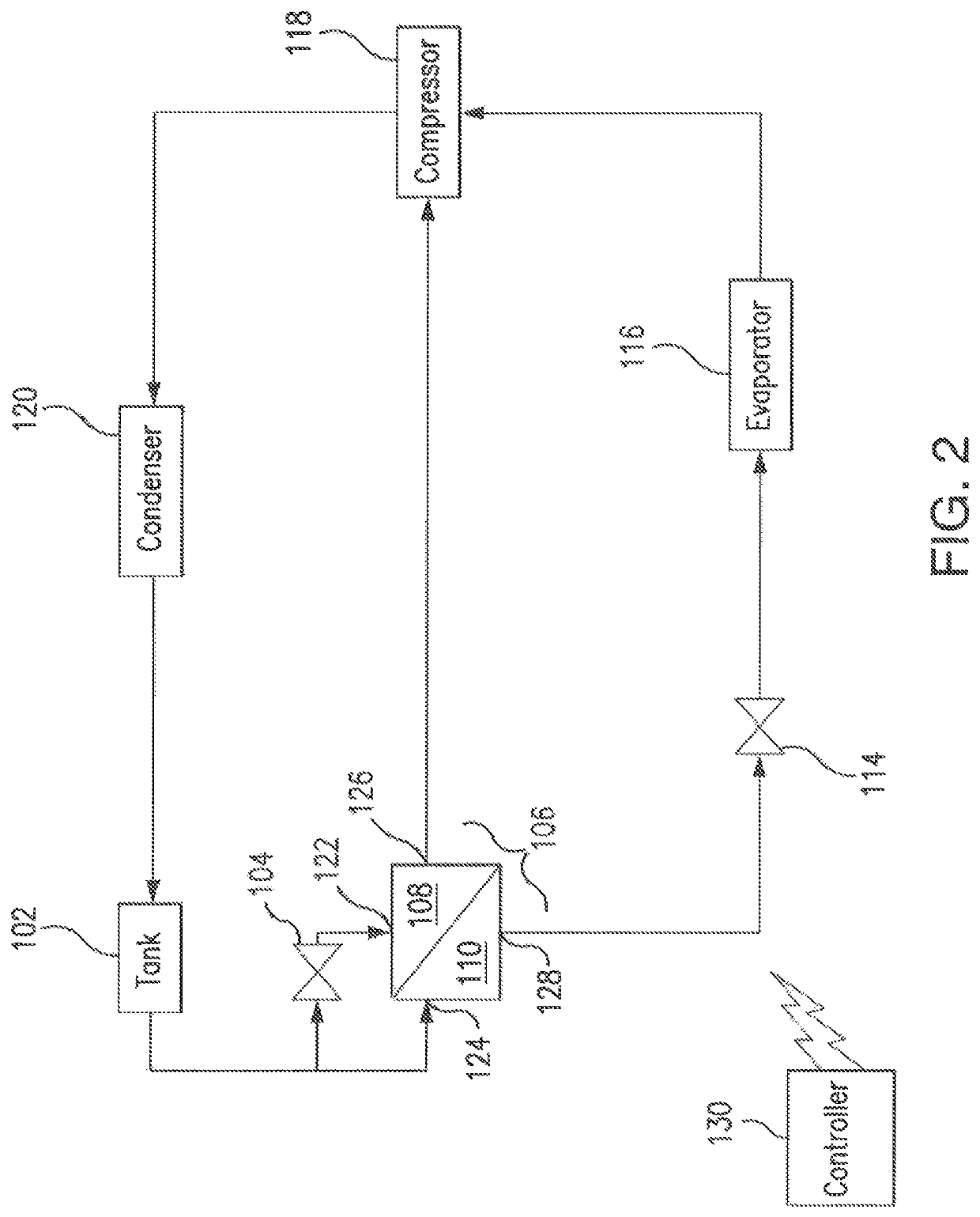
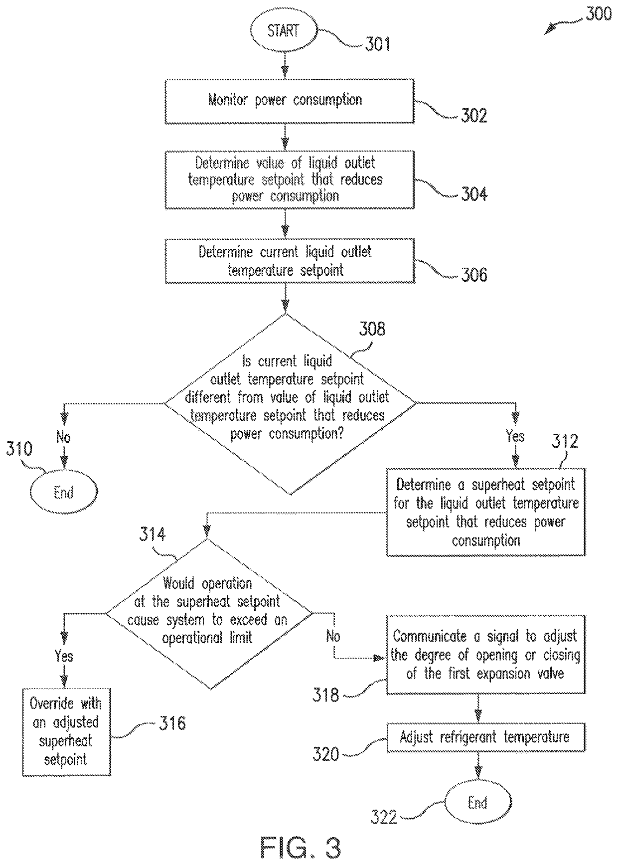
[0005]This disclosure contemplates an unconventional cooling system that minimizes power consumption and increases system efficiency by determining optimal liquid subcooling based on ambient temperature and load. Furthermore, this disclosure contemplates using a single valve to control vapor outlet superheat and maintain liquid outlet setpoint, which is dependent on the degree of subcooling. Certain embodiments of the system will be described below.
[0009]Certain embodiments may provide one or more technical advantages. For example, power consumption may be minimized by determining optimal liquid subcooling based on ambient condition and load. Additionally, certain embodiments conserve cost by using one valve as opposed to two.

Problems solved by technology

Overcooling the liquid may result in diminished returns, and thus a lack of efficiency.
However, using two valves adds cost and complexity to the system.

Method used


Image

  • Self-optimizing subcooler control
  • Self-optimizing subcooler control
  • Self-optimizing subcooler control

Examples


Embodiment Construction

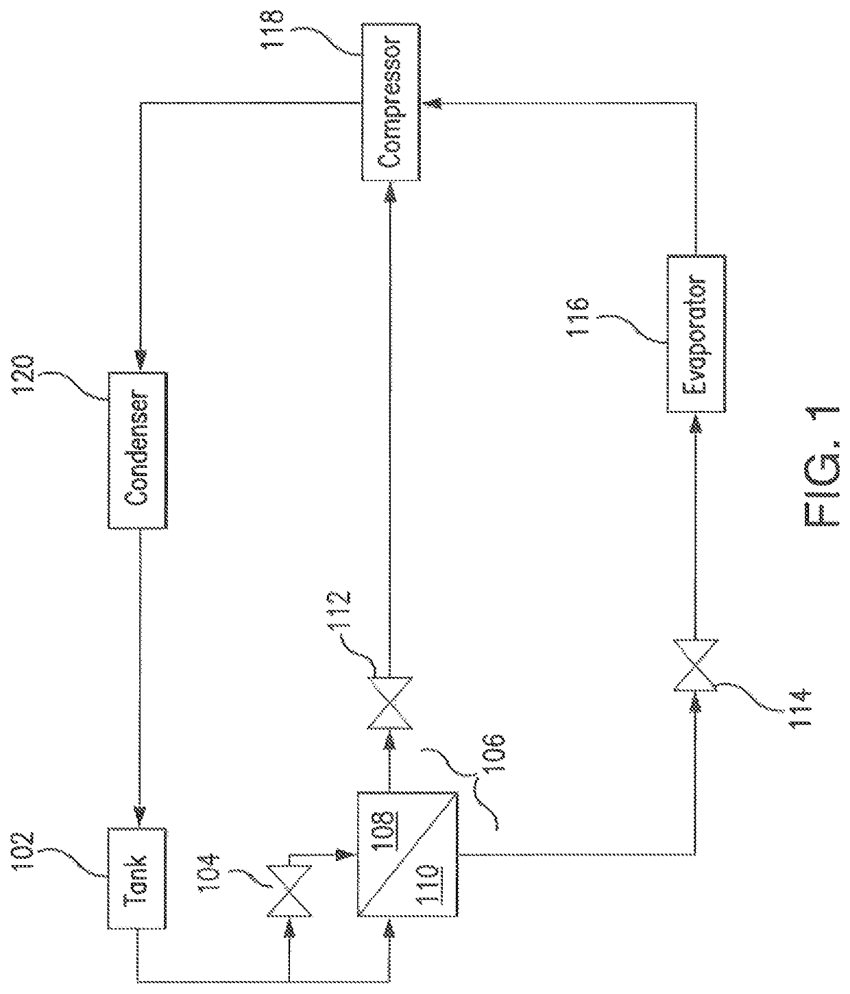
[0019]Embodiments of the present disclosure and its advantages are best understood by referring to FIGS. 1 through 7 of the drawings, like numerals being used for like and corresponding parts of the various drawings.

[0020]Generally, a refrigeration cycle includes circulating refrigerant though one or more refrigeration components, including at least one compressor, a heat exchanger (e.g., a condenser), at least one valve, and one or more evaporators. To ensure the system operates as intended, each system requires sufficient power, which may vary based on the refrigeration load. The present disclosure contemplates a system and method for efficiency operating a refrigeration system.

[0021]For example, FIG. 1 illustrates a conventional refrigeration system. The refrigeration system of FIG. 1 includes tank 102, first expansion valve 104, subcooler 106, first path 108, second path 110, compressor path expansion valve 112, second expansion valve 114, evaporator 116, compressor 118, and con...


PUM


Abstract

According to certain embodiments, a method comprises determining a liquid outlet temperature setpoint for refrigerant discharged from a liquid outlet of a subcooler. The liquid outlet corresponds to a hot-side path of the subcooler that receives refrigerant directly from a tank, cools the refrigerant by an exchange of heat with a cold-side path of the subcooler that receives the refrigerant from the tank via an inlet expansion valve, and discharges the refrigerant to an evaporator via an outlet expansion valve. The method further comprises determining a superheat setpoint for the refrigerant discharged to a compressor via a vapor outlet of the cold-side path. The superheat setpoint is determined based on the liquid outlet temperature setpoint. The method further comprises adjusting a temperature of the refrigerant discharged to the compressor based on the superheat setpoint.

Description

TECHNICAL FIELD[0001]This disclosure relates generally to a climate control system. More specifically, this disclosure relates to a refrigeration system including a subcooler.BACKGROUND[0002]Refrigeration systems can be used to regulate the environment within an enclosed space. Various types of refrigeration systems, such as residential and commercial, may be used to maintain cold temperatures within an enclosed space such as a refrigerated case. An example of a refrigerated case includes a grocery store case that stores fresh or frozen food products. To maintain cold temperatures within refrigerated cases, refrigeration systems control the temperature and pressure of refrigerant as it moves though the refrigeration system. When controlling the temperature and pressure of the refrigerant, refrigeration systems consume power. It is generally desirable to operate refrigeration systems efficiently in order to avoid wasting power.SUMMARY OF THF DISCLOSURE[0003]Refrigeration systems cycl...

Claims


Application Information

Patent Timeline
Patent Type & Authority Patents(United States)
IPC IPC(8): F25D17/02F25B40/02F25B25/02
CPCF25B40/02F25B25/02F25D17/02F25B2400/13F25B49/02F25B2600/2509F25B41/39
Inventor HJORTLAND, ANDREW
Owner HEATCRAFT REFRIGERATION PRODS
Learn More