Display apparatus
a technology of display apparatus and display housing, which is applied in the direction of identification means, instruments, computing, etc., can solve the problems of affecting the appearance of the display guidance apparatus, the undesirable shape of the light guide window on the outer wall of the housing, and the inability to properly adjust the display device, etc., to achieve the effect of not impairing the appearance of the apparatus
- Summary
- Abstract
- Description
- Claims
- Application Information
AI Technical Summary
Benefits of technology
Problems solved by technology
Method used
Image
Examples
first embodiment
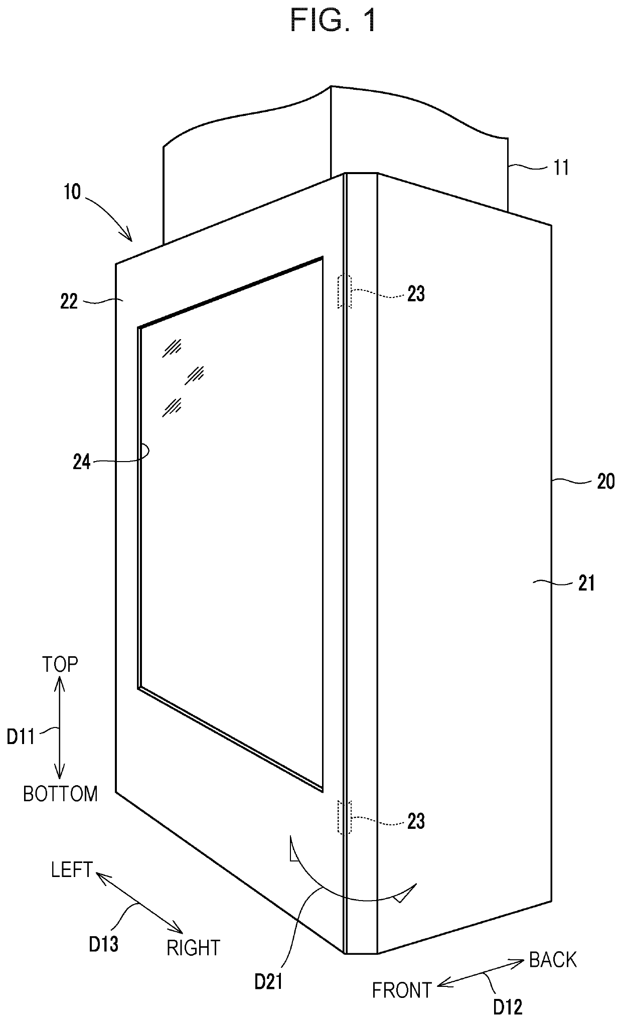
[0030]FIG. 1 is a perspective view showing a display guidance apparatus 10 (an example of a display apparatus of the present disclosure) according to a first embodiment of the present disclosure. The display guidance apparatus 10 is an electronic guide display apparatus installed in a concourse such as a department store, a shopping mall, an airport, a station and an apparatus that displays and provides the floor guide, shop information, peripheral area information, and the like of a facility to a user of the facility.
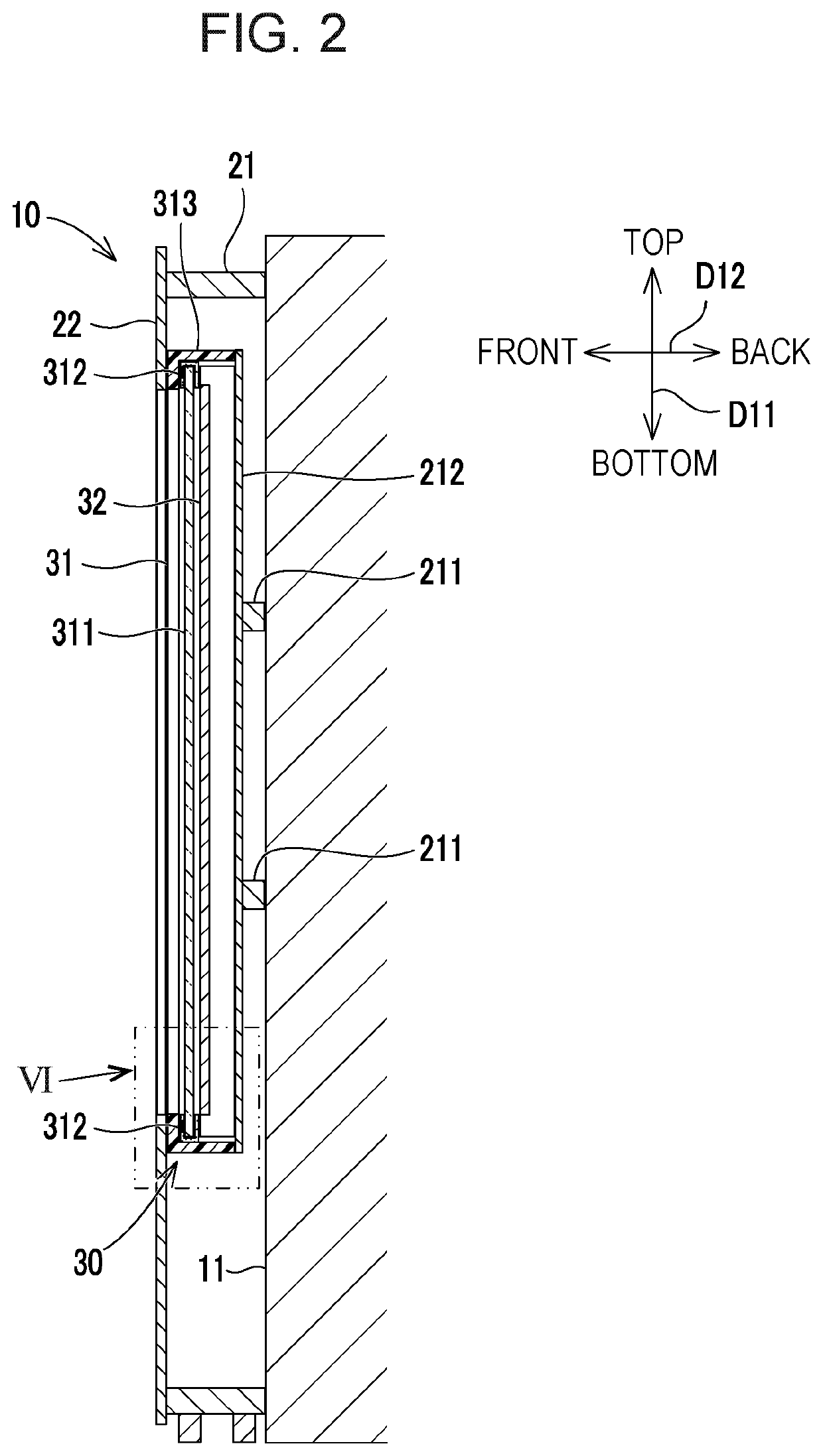
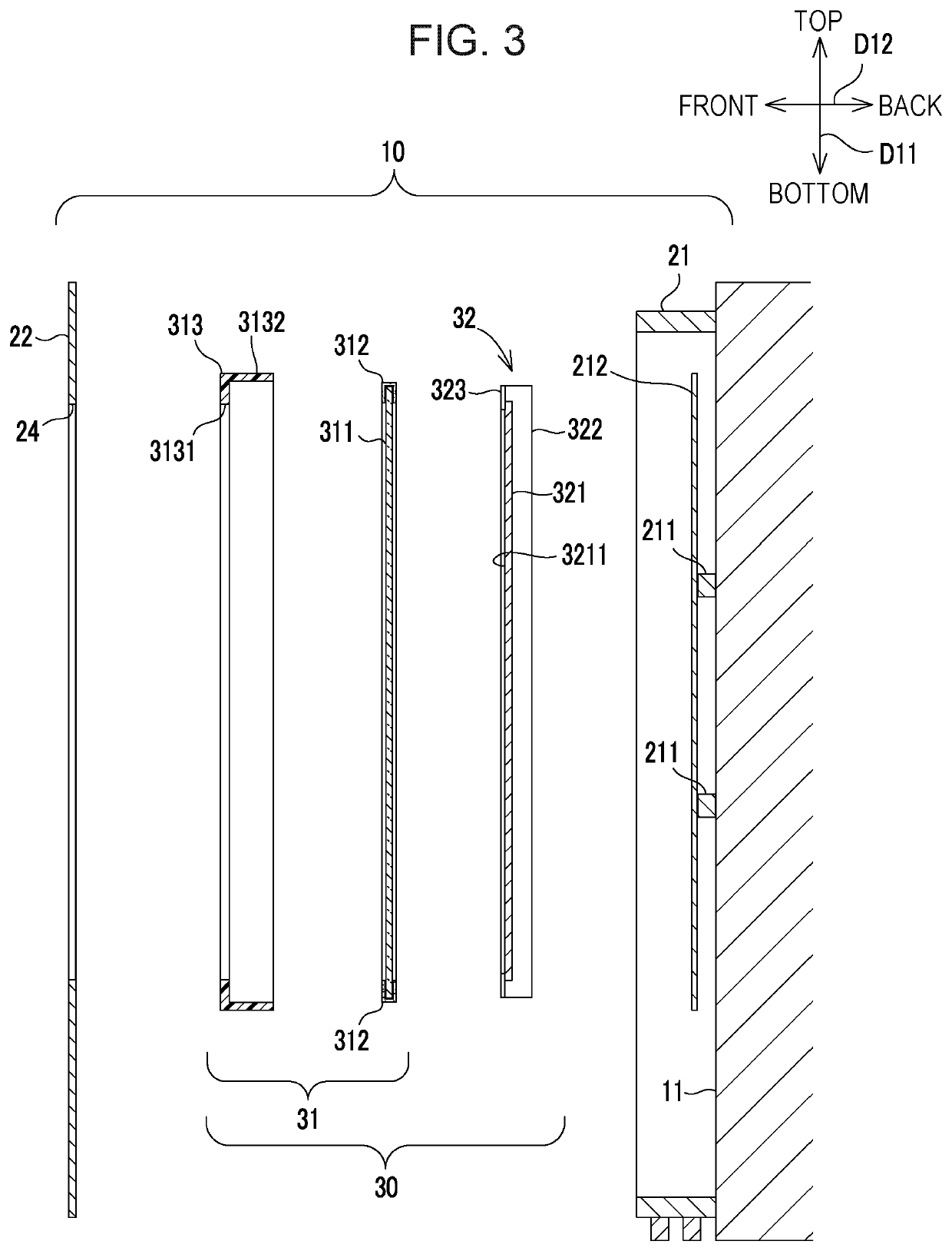
[0031]As shown in FIG. 1, the display guidance apparatus 10 is provided on a wall surface 11 such as a pillar of a facility in a concourse. The display guidance apparatus 10 generally includes a cabinet 20 (an example of an outer housing of the present disclosure) and a display unit 30 (see FIG. 2) accommodated inside the cabinet 20.
[0032]As shown in FIGS. 1 and 2, the cabinet 20 supports a display unit 30 (see FIG. 2) in a state of being embedded therein and includes ...
second embodiment
[0060]Hereinafter, a second embodiment of the present disclosure will be described with reference to FIGS. 12 and 13. FIG. 12 is an enlarged view showing the periphery of a light guide film 405 (an example of a light guide member of the present disclosure) in the display guidance apparatus 10 according to the present embodiment. FIG. 13 is an enlarged view showing the progression of the IR light incident on the light guide film 405. In this embodiment, the light receiving sensor 51 is provided on the back surface side inside the liquid crystal display apparatus 32. More specifically, the light receiving sensor 51 is provided near a right-side wall 3221 of the support frame 322. The light receiving surface 511 of the light receiving sensor 51 is not directed to the front surface side but directed to the right-side wall 3221.
[0061]A through-hole 3222 penetrating the right-side wall 3221 is formed on the back surface side of the right-side wall 3221. The light receiving sensor 51 is pr...
third embodiment
[0065]Hereinafter, a third embodiment of the present disclosure will be described with reference to FIG. 14. FIG. 14 is an enlarged view showing the periphery of a light guide film 406 (an example of a light guide member of the present disclosure) in the display guidance apparatus 10 according to the present embodiment. The present embodiment is different from the above-described second embodiment in that the light guide member 53 is not provided, and the light guide film 406 having a third light guide portion 4053 is provided. The light guide film 406 has the above-described first light guide portion 4051 and the second light guide portion 4052, and further, the third light guide portion 4053 is provided continuously to the second light guide portion 4052. The third light guide portion 4053 is bent at a right angle from the second light guide portion 4052 to the left side and is inserted through the through-hole 3222. The end surface 44, which is the extended end of the third light...
PUM
| Property | Measurement | Unit |
|---|---|---|
| thickness | aaaaa | aaaaa |
| thickness | aaaaa | aaaaa |
| swelling | aaaaa | aaaaa |
Abstract
Description
Claims
Application Information
 - R&D
- Intellectual Property
- Life Sciences
- Materials
- Tech Scout
- Unparalleled Data Quality
- Higher Quality Content
- 60% Fewer Hallucinations
Browse by: Latest US Patents, China's latest patents, Technical Efficacy Thesaurus, Application Domain, Technology Topic, Popular Technical Reports.
© 2025 PatSnap. All rights reserved.Legal|Privacy policy|Modern Slavery Act Transparency Statement|Sitemap|About US| Contact US: help@patsnap.com


