Wing flex apparatus for agricultural planter

a planter and flexing technology, applied in the field of forward folding agricultural implements, can solve the problems of limited operation of the folding function of such planters, and achieve the effect of reducing the angular rotation of the ground engaging tool

Active Publication Date: 2020-10-27
KINZE MFG INC
View PDF23 Cites 2 Cited by
  • Summary
  • Abstract
  • Description
  • Claims
  • Application Information

AI Technical Summary

Benefits of technology

[0006]Therefore, it is a primary object, feature, and / or advantage of the invention to improve on and / or overcome the deficiencies in the art.
[0007]It is another object, feature, and / or advantage of the invention to provide an agricultural implement with ground engaging tools.
[0008]It is yet another object, feature, and / or advantage of the invention to provide an apparatus and system to assist with mounting ground engaging tools on an agricultural implement with at least one folding wing.
[0009]It is a further object, feature, and / or advantage of the invention to provide an apparatus and system to assist with spacing of the ground engaging tools mounted on the agricultural implement with at least one folding wing.
[0010]It is still a further object, feature, and / or advantage of the invention to provide an apparatus and system that allows a ground engaging tool to be mounted on the agricultural implement proximate to the hinge or pivot point.
[0011]It is still yet a further object, feature, and / or advantage of the invention to provide an apparatus and system that dampens the angular rotation of a ground engaging tool attached proximate to the hinge or pivot point of an agricultural implement.

Problems solved by technology

The folding functions of such planters have, to varying degrees, operating limitations due to their design and the environment in which they operate.
However, when the adjacent row units that are attached directly to the frame of a first and second wing section, on opposing sides of the hinge or pivot point, the deflection of the hinge may cause the row unit attached to the first section to come into contact with the adjacent row unit attached to the second wing section.

Method used


Image

  • Wing flex apparatus for agricultural planter
  • Wing flex apparatus for agricultural planter
  • Wing flex apparatus for agricultural planter

Examples


Embodiment Construction

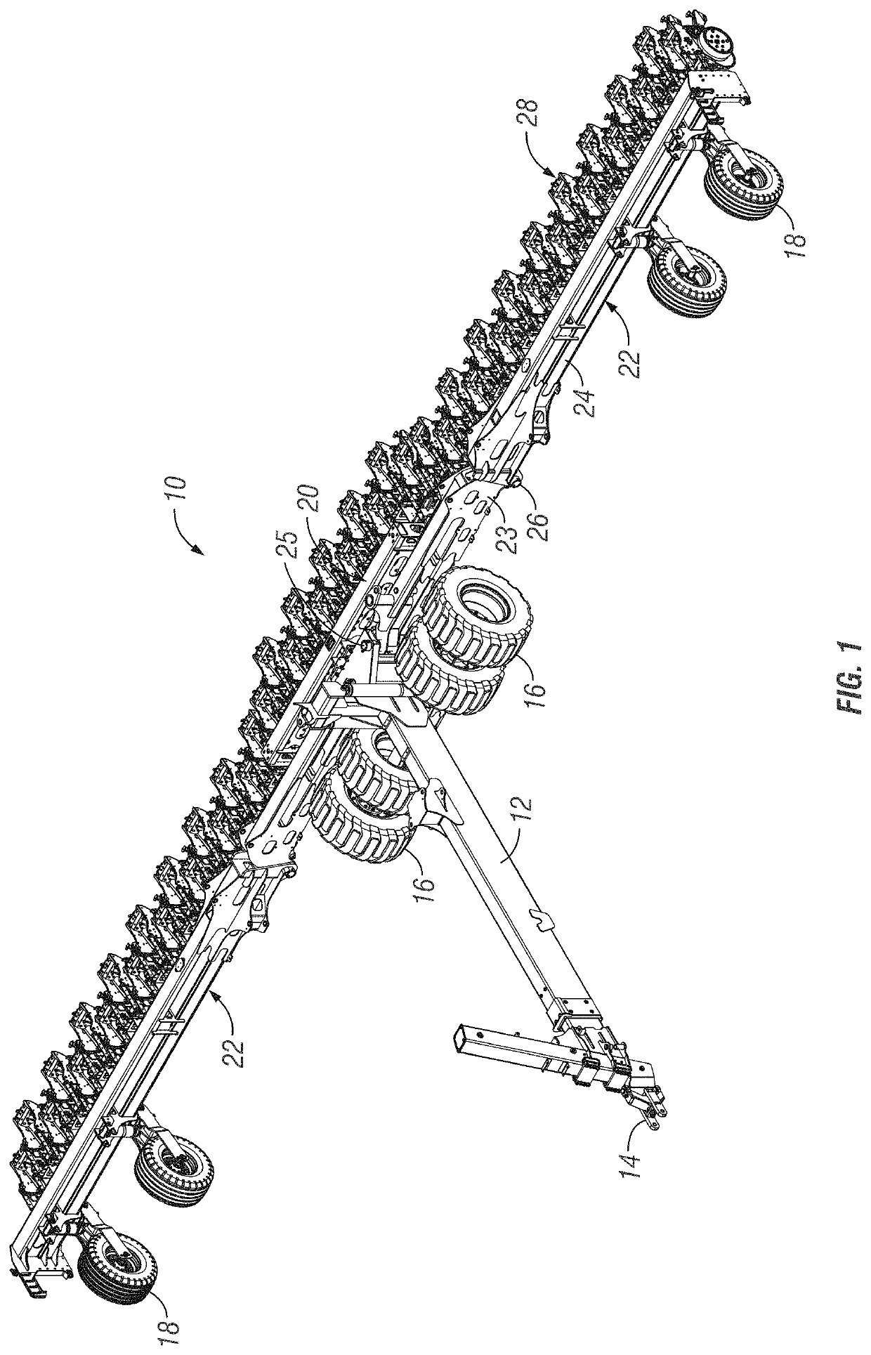
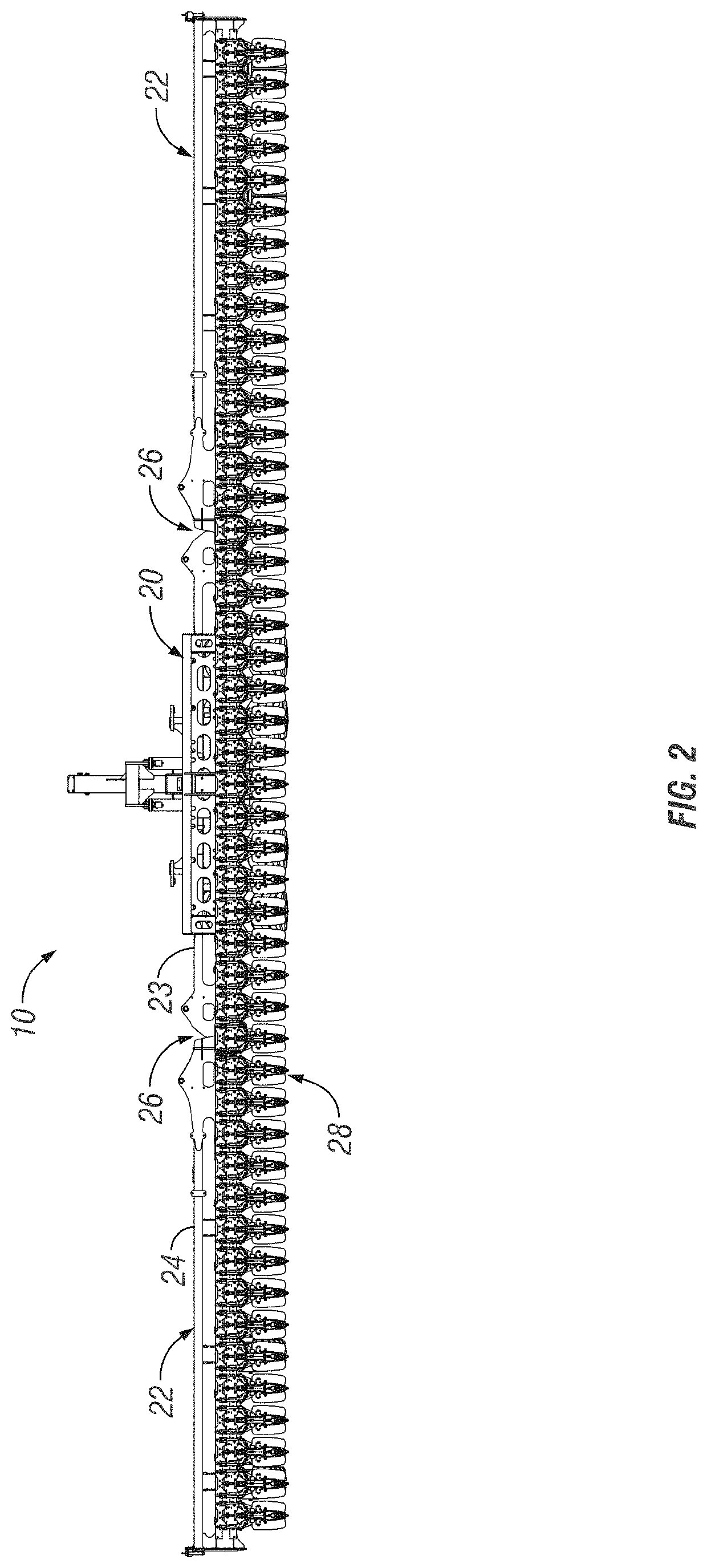
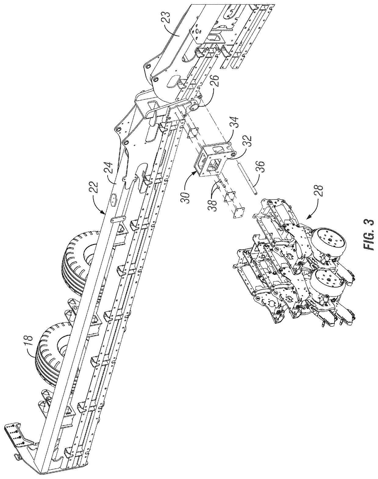
[0025]An apparatus and system for mounting a ground engaging tool on an agricultural implement proximate to the location of a pivot joint is disclosed. An agricultural implement may be used to plant seed, apply fertilizer, work ground, etc. For example, an agricultural implement referred to as a plow may be used for turning over the soil, an agricultural planter may be used to plant the seed, and an applicator may be used to apply chemicals. Generally, agricultural implements comprise various types of ground engaging tools that are configured based on the agricultural operation to be performed. For example, a plow may include a cutting disk, plow shank, or tines that are attached to a main toolbar and / or wing(s) for loosening and turning over the soil. A planter may include an assembly known as a row unit, the row unit generally configured to insert a seed into the soil. Depending on the type of seed being planted and other conditions, such as the soil type or expected climate / growi...


PUM


Abstract

A system and apparatus for attaching ground engaging tools proximate to the pivot point of an agricultural implement is provided. The system includes a flex apparatus configured to be operatively attached proximate to the pivot point of an agricultural implement by a pin. The flex apparatus may be configured to rotate as the pivot point of the agricultural implement flexes. The flex apparatus may include tracks, slots, or the like, configured to dampen the rotation of the flex apparatus relative to the flex of the pivot point of the agricultural implement. The size, location and orientation of the tracks, slots, or the like, may be configured to provide varying amounts of rotation of the flex apparatus relative to the flex of the pivot point of the agricultural implement. Furthermore, the flex apparatus includes holes, slots, grooves, or the like, configured for attaching a ground engaging tool to the flex apparatus.

Description

CROSS-REFERENCE TO RELATED APPLICATIONS[0001]This application is a continuation of PCT / US2016 / 054797, filed Sep. 30, 2016, which claims priority under 35 U.S.C. § 119 to Provisional Application Ser. No. 62 / 235,624, filed Oct. 1, 2015, herein incorporated by reference in their entirety.FIELD OF THE INVENTION[0002]The invention relates generally to a forward folding agricultural implement. More specifically, but not exclusively, the invention relates to a forward folding agricultural implement frame. Even more specifically, but not exclusively, the invention relates to the mounting of a ground engaging tool proximate to a flex point of an agricultural implement frame.BACKGROUND OF THE INVENTION[0003]As the power of tractors and agricultural efficiency has increased, agricultural implements, such as planters have increased in span, or width, to accommodate larger numbers of individual row units. Large planters generally include a main frame having a forward hitch assembly for drawing b...

Claims


Application Information

Patent Timeline
Patent Type & Authority Patents(United States)
IPC IPC(8): A01B73/04A01B73/06A01C7/20F16C11/12
CPCF16C11/12A01B73/065A01C7/208A01B73/044
Inventor BLACKWELL, ROBERT
Owner KINZE MFG INC
Why Eureka
Try Eureka