Dimple patterns for golf balls

a golf ball and pattern technology, applied in the field of golf ball dimple patterns, can solve the problems of difficult to devise new symmetric patterns, less than optimal surface coverage, and other disadvantageous dimple arrangements

Active Publication Date: 2020-10-27
ACUSHNET CO
View PDF13 Cites 7 Cited by
  • Summary
  • Abstract
  • Description
  • Claims
  • Application Information

AI Technical Summary

Problems solved by technology

Because the number of symmetric solid plane systems useful in designing dimple patterns is limited, it can be difficult to devise new symmetric patterns.
Moreover, dimple patterns based on some geometric shapes result in less than optimal surface coverage and other disadvantageous dimple arrangements.

Method used


Image

  • Dimple patterns for golf balls
  • Dimple patterns for golf balls
  • Dimple patterns for golf balls

Examples


examples

[0069]The following non-limiting examples demonstrate dimple patterns of golf balls made in accordance with the present invention. The examples are merely illustrative of the preferred embodiments of the present invention, and are not to be construed as limiting the invention, the scope of which is defined by the appended claims.

Non-Limiting Exemplar Dimple Pattern 1

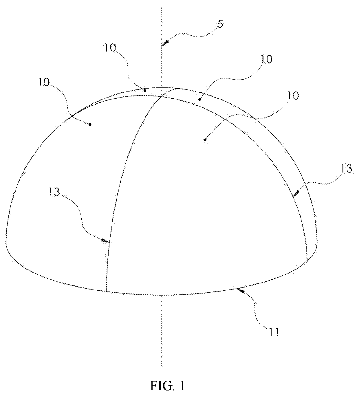
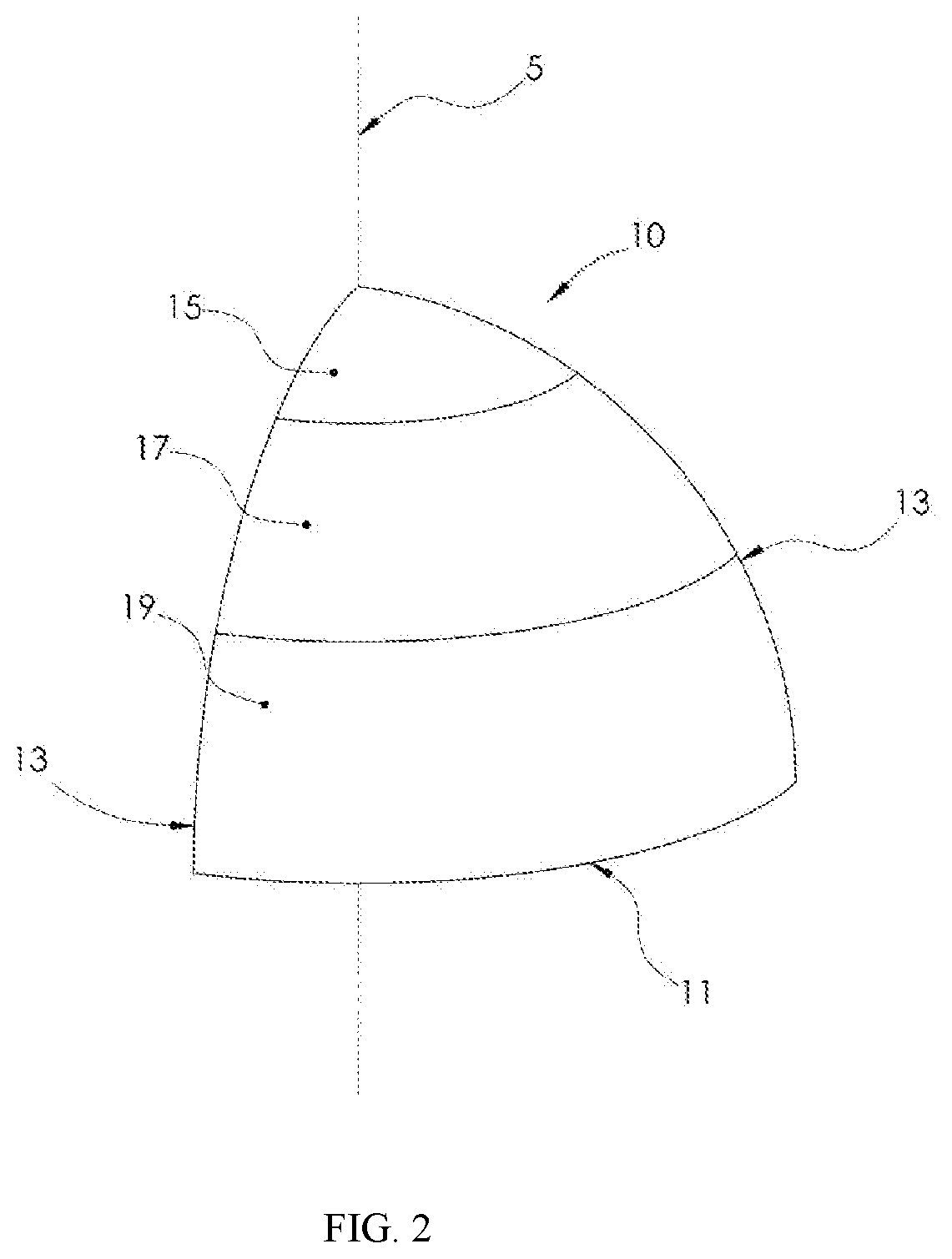
[0070]A triangular section of a dimple pattern based on a square dipyramid according to a particular embodiment of the present invention is illustrated in FIGS. 4A-4C. FIGS. 4A-4C show a triangular dimple section 10 packed with dimples into a dimple arrangement consisting of: thirty-two non-intersecting dimples, one polar dimple, ten side edge dimples, and six non-shared equatorial dimples. Thus, a golf ball having a dimple pattern based on a square dipyramid, with each triangular dimple section having the dimple arrangement shown in FIGS. 4A-4C, has a total of 346 dimples, with a surface coverage of about 82.1%. The gol...


PUM


Abstract

A golf ball dimple pattern based on a square dipyramid, i.e., two square pyramids connected base-to-base, is disclosed. The dimples are arranged within four substantially identical triangular sections on each of two substantially identical hemispheres of the ball.

Description

FIELD OF THE INVENTION[0001]The present invention relates to golf ball dimple patterns based on a square dipyramid, wherein the dimples are arranged within four substantially identical triangular sections on each of the two hemispheres of the ball.BACKGROUND OF THE INVENTION[0002]Golf ball manufacturers make substantial efforts to maximize the aerodynamic efficiency of golf balls, though they are closely controlled by golf's national governing body, the United States Golf Association (U.S.G.A.). One U.S.G.A. requirement is that golf balls have aerodynamic symmetry. Aerodynamic symmetry allows the ball to fly with a very small amount of variation no matter how the golf ball is placed on the tee or ground. In order to improve aerodynamic symmetry, many dimple patterns are based, for example, on geometric shapes, the five Platonic Solids, and the thirteen Archimedean Solids. Because the number of symmetric solid plane systems useful in designing dimple patterns is limited, it can be di...

Claims


Application Information

Patent Timeline
Patent Type & Authority Patents(United States)
IPC IPC(8): A63B37/00
CPCA63B37/002A63B37/0006A63B37/0021A63B37/0012
Inventor MADSON, MICHAEL R.
Owner ACUSHNET CO
Why Eureka
Try Eureka