
Toothed belt transmission

a transmission and toothed belt technology, applied in the direction of gearing, mechanical equipment, hoisting equipment, etc., can solve the problems of noise and noise occurrence, and achieve the effect of improving the anchoring effect, noise and vibration, and reducing the wear of the tooth bottom parts

Active Publication Date: 2020-10-27
TSUBAKIMOTO CHAIN CO
View PDF33 Cites 0 Cited by
  • Summary
  • Abstract
  • Description
  • Claims
  • Application Information

AI Technical Summary

Benefits of technology

[0006]Therefore, the present invention has been made to solve the above problems and has an object of providing a toothed belt transmission that reduces noise and vibration resulting from the engagement between a toothed belt and a toothed pulley, and that improves the durability of the toothed belt.
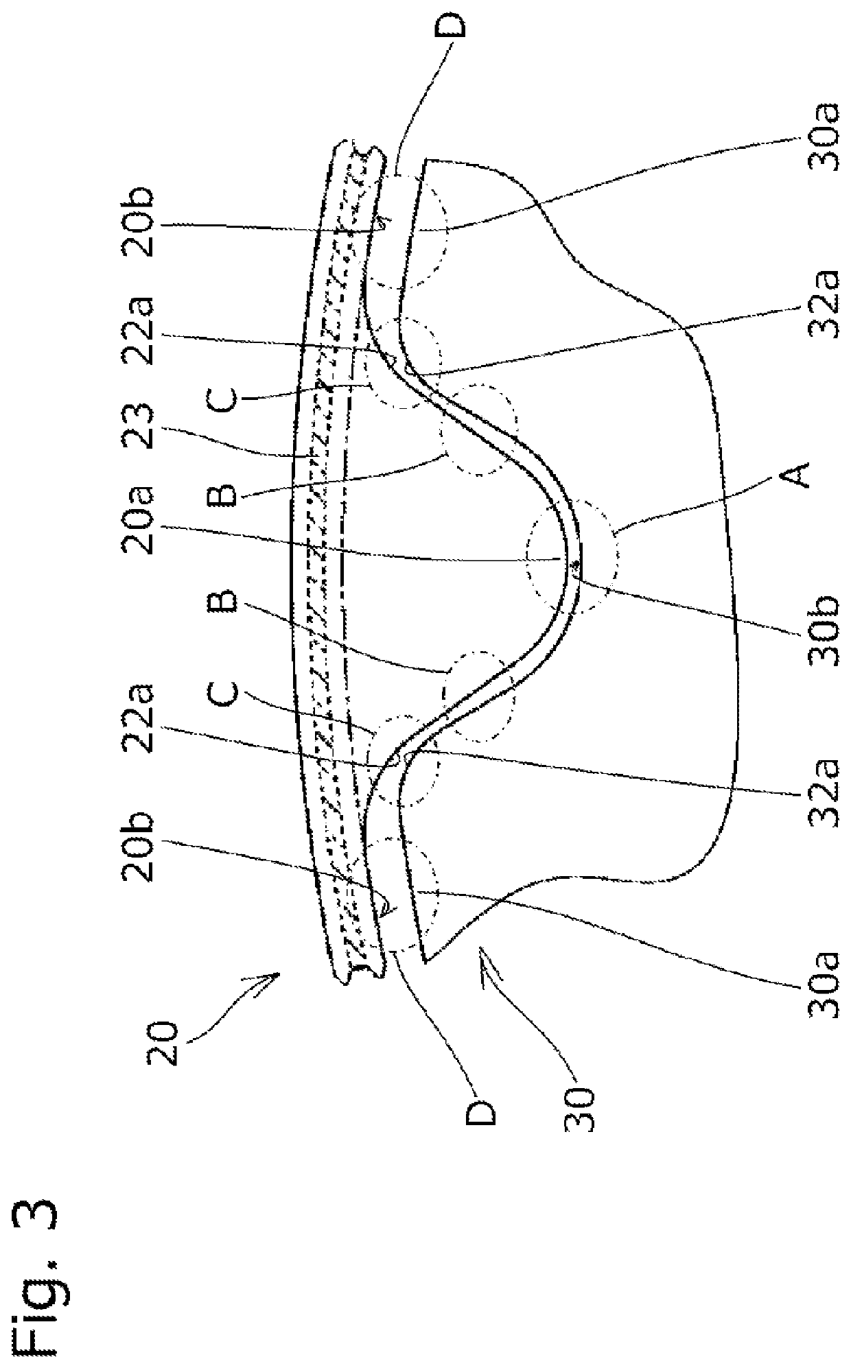
[0009]Thus, after a shock caused when the toothed belt and the toothed pulley start engaging with each other is absorbed by the elastic deformation of the tooth tip parts of the toothed belt made of an elastic material such as rubber, it is possible to cause the tooth bottom parts of the toothed belt and the tooth tip parts of the toothed pulley to contact each other. Therefore, noise and vibration resulting from the contact between the tooth bottom parts of the toothed belt in which a core wire made of a hard material such as glass fibers and aramid fibers is buried and the tooth tip parts of the toothed pulley made of metal and the like may be reduced.
[0010]In addition, since it is possible to reduce the wear of the tooth bottom parts of the toothed belt resulting from the friction between the tooth bottom parts of the toothed belt in which the hard core wire is buried and the tooth tip parts of the toothed pulley made of the metal by causing the tooth bottom parts of the toothed belt and the tooth tip parts of the toothed pulley to contact each other after the shock caused when the toothed belt and the toothed pulley engage with each other is absorbed by the elastic deformation of the tooth tip parts of the toothed belt, the service life of the toothed belt may be prolonged. In addition, since it is possible to improve an anchor effect by which belt teeth are caught on pulley teeth by setting the height of the toothed belt to be longer, the occurrence of tooth skipping may be prevented. Thus, the wider usage of a toothed belt transmission can be accomplished, allowing the toothed belt to be driven at higher speed, for example.
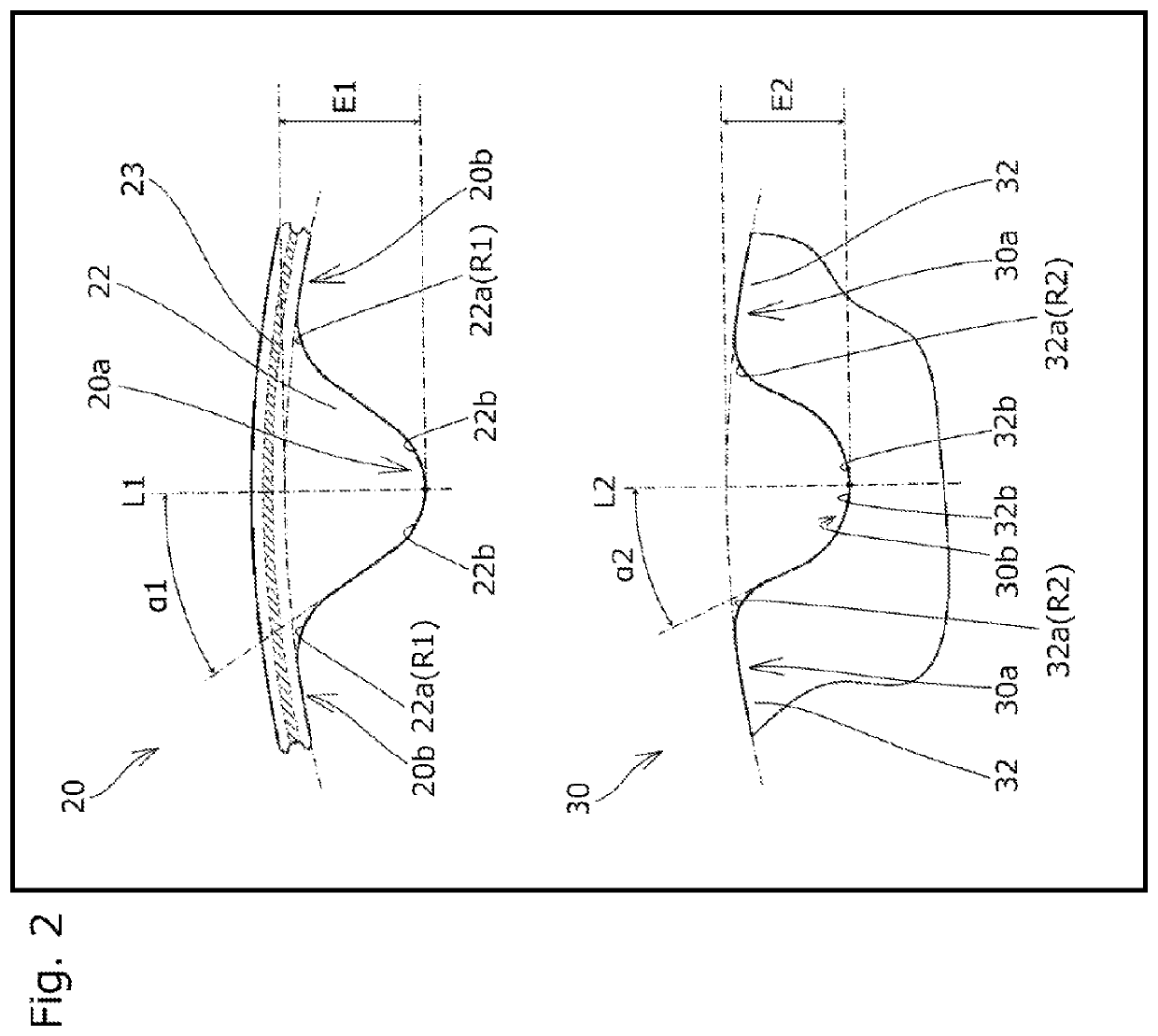
[0011]According to another embodiment of the present invention, a curvature radius of the tooth root-side concave curved parts of the tooth surfaces of the belt teeth is set to be greater than or equal to a curvature radius of the tooth tip-side convex curved parts of the tooth surfaces of the pulley teeth. Thus, during the engagement between the toothed belt and the toothed pulley, it is possible to cause the tooth root-side concave curved parts of the belt teeth and the tooth tip-side convex curved parts of the toothed pulley to reliably contact each other. Therefore, the following effect may be produced besides causing the tooth root-side concave curved parts of the belt teeth and the tooth tip-side convex curved parts of the toothed pulley to smoothly contact each other to absorb the shock caused when the toothed belt and the toothed pulley start engaging with each other. That is, the tooth root-side concave curved parts of the belt teeth and the tooth tip-side convex curved parts of the toothed pulley are caused to contact each other in a state in which the toothed belt and the toothed pulley engage with each other, whereby the belt teeth are prevented from moving in a back and forth direction (belt longitudinal direction) with respect to the pulley teeth on the tooth root-side of the belt teeth. Therefore, even in a case in which the toothed belt transmission is applied to a device that requires reciprocating operation or an engine in which explosion fluctuation peculiar to an automobile occurs, noise and vibration caused when the belt teeth and the pulley teeth collide with each other in the back and forth direction may be reduced. In addition, since a shearing force applied to the tooth roots of the belt teeth is similarly reduced, the lack of the teeth or the like may be prevented. As a result, the service life of the toothed belt may be prolonged.
[0012]According to another embodiment of the present invention, a pressure angle of the tooth surfaces of the belt teeth is set to be greater than a pressure angle of the tooth surfaces of the pulley teeth. Therefore, when the toothed belt and the toothed pulley engage with each other, gaps are produced between the tooth surfaces of the belt teeth and the pulley teeth at the lateral parts of the belt teeth and the pulley teeth. Thus, compressed air between the tooth surfaces may be released in a tooth trace direction without being trapped to avoid a cause of engagement noise resulting from an explosive sound, while an engagement shock may be elastically relaxed by the gaps between the tooth surfaces. In addition, since it is possible to release the elastic material of the elastically-deforming belt teeth into the gaps between the tooth surfaces, colliding energy may be relaxed. Moreover, since the elastic material of the elastically-deforming belt teeth fill in the gaps between the tooth surfaces, an anchor effect by which the belt teeth are caught on the pulley teeth is improved. As a result, the occurrence of tooth skipping may be prevented.

Problems solved by technology

Therefore, since accessories are simple instead of a noise-proof cover such as a conventional timing belt for an engine, passengers are susceptible to noise.
After exhaustively considering a cause of the occurrence of noise, the present applicant has found that the collision between the tooth bottom parts of a toothed belt and the tooth tip parts of a toothed pulley results in the cause of the occurrence of the noise.

Method used


Image

  • Toothed belt transmission
  • Toothed belt transmission
  • Toothed belt transmission

Examples


Embodiment Construction

[0021]Hereinafter, a description will be given, with reference to the drawings, of a toothed belt transmission 10 according to an embodiment of the present invention.

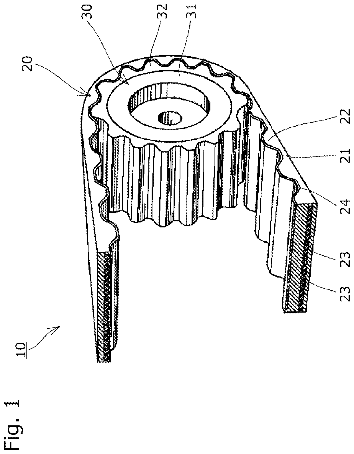
[0022]First, as shown in FIG. 1, the toothed belt transmission 10 is constituted of a toothed belt 20 having belt teeth 22 on its inner periphery side and a plurality of toothed pulleys 30 having pulley teeth 32 on their outer periphery sides and transmits rotation from a driving-side toothed pulley 30 to a driven-side toothed pulley 30 with the toothed belt 20 wound around the toothed pulleys 30.

[0023]As shown in FIG. 1, the toothed belt 20 has a belt body 21 and a plurality of belt teeth 22 formed on the inner peripheral surface of the belt body 21 at prescribed intervals in a belt longitudinal direction. The belt body 21 and the belt teeth 22 are made of an elastic material such as rubber.

[0024]In addition, as shown in FIGS. 1 and 2, a core wire 23 made of glass fibers, aramid fibers, or the like is buried in the bel...


PUM

PropertyMeasurementUnit
heightaaaaaaaaaa
curvature radiusaaaaaaaaaa
pressure angleaaaaaaaaaa

Abstract

The present invention provides a toothed belt transmission that reduces noise and vibration resulting from the engagement between a toothed belt and a toothed pulley, and that improves the durability of the toothed belt. The toothed belt transmission in which a tooth height of a toothed belt and a tooth height of a toothed pulley are set so that when the toothed belt and the toothed pulley start engaging with each other, tooth tip parts of the toothed belt and tooth bottom parts of the toothed pulley contact each other before tooth bottom parts of the toothed belt and tooth tip parts of the toothed pulley contact each other.

Description

BACKGROUND OF THE INVENTION1. Field of the Invention[0001]The present invention relates to a toothed belt transmission that transmits rotation, with a toothed belt having belt teeth and a toothed pulley having pulley teeth being engaged with each other.2. Description of the Related Art[0002]Conventionally, toothed belt transmissions each constituted of a toothed belt having belt teeth and a toothed pulley having pulley teeth have been widely used for the purpose of, for instance, transmitting rotation between a driving shaft and a driven shaft as in the transmission of rotation between a crank shaft and a cam shaft in automobile engines (see, for example, Japanese Patent Application Laid-open Nos. 2010-101395 and 2010-096257).[0003]Since such toothed belt transmissions cause noise when driven, various attempts, such as forming belt teeth and pulley teeth in a helical tooth shape by being cut diagonally with respect to a rotational axis, have been made to reduce the noise.SUMMARY OF ...

Claims


Application Information

Patent Timeline
Patent Type & Authority Patents(United States)
IPC IPC(8): F16H7/02F16G1/10F16G1/28F16H55/17
CPCF16H55/171F16G1/28F16G1/10F16H7/023
Inventor KONNO, MASAHIKOSHIMIZU, SHOICHIROTOMOBUCHI, MASATOKANAMORI, MASARU
Owner TSUBAKIMOTO CHAIN CO
Learn More