
Systems and methods for automatic camera installation guidance (CIG)

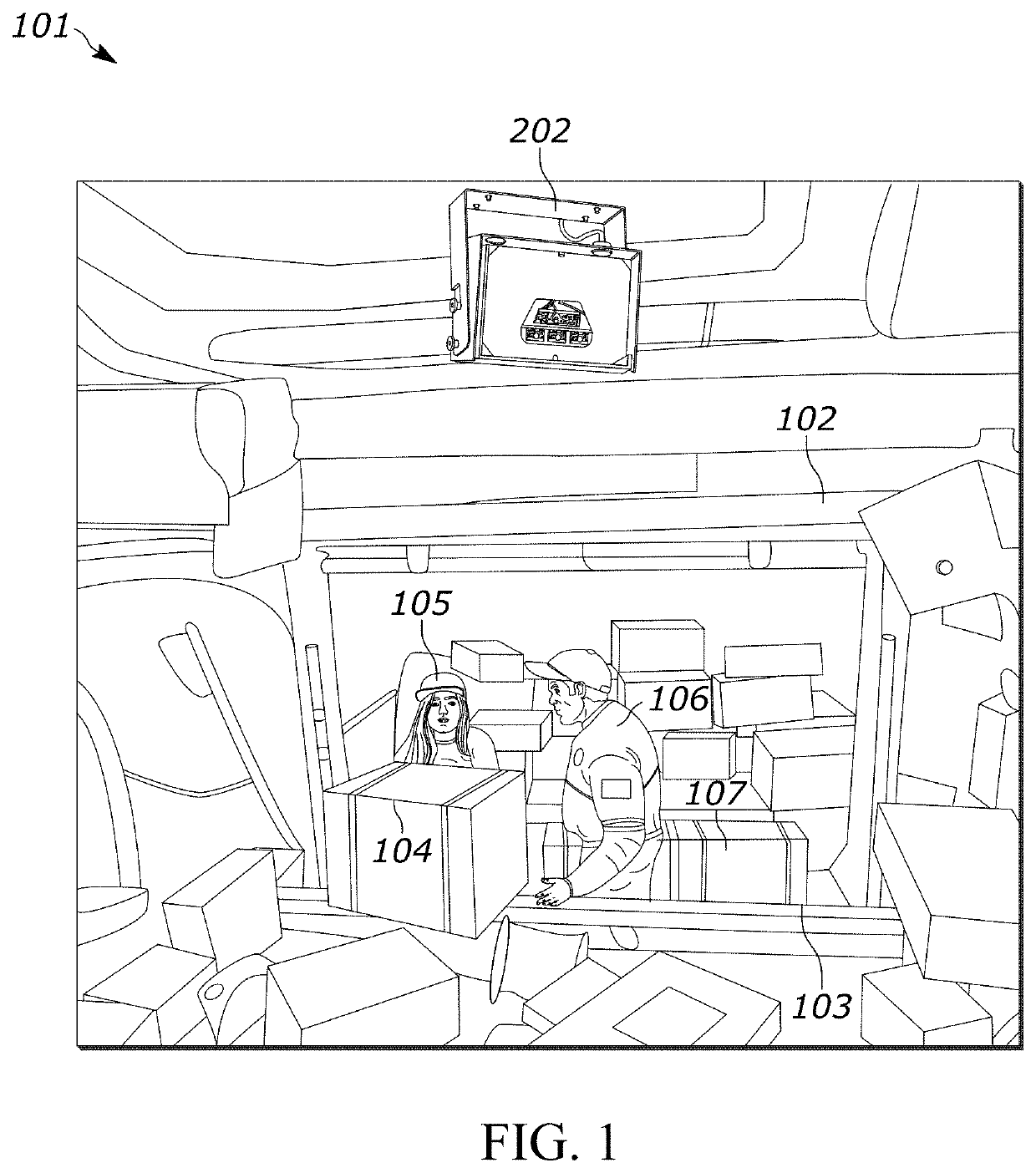
a technology of automatic camera installation and system, applied in the field of automatic camera installation guidance system, can solve the problems of a large number of inefficiencies, high cost, and high cost, and achieve the effects of reducing the cost of installation

Active Publication Date: 2020-10-27
ZEBRA TECH CORP
View PDF8 Cites 10 Cited by
  • Summary
  • Abstract
  • Description
  • Claims
  • Application Information

AI Technical Summary

Problems solved by technology

However, problems arise from such traditional analytics systems.
Thus, the traditional orientation process is very time consuming and inaccurate due to the inherent inaccuracies associated with human visual image inspection.
Moreover, large-scale installations may involve orienting dozens of LMUs, which can quickly compound these inefficiencies.
However, the direct 3D matching technique is not robust in that it lacks stable and repeatable results, is also sensitive to partial structures, and involves in high computation complexity.
In addition, the matching is not accurate, which generally leads to erroneous and generally inaccurate reporting.
Point cloud clustering, however, is also not robust as it lacks stable and repeatable results, in particular, it suffers from uncontrollable 3D data segmentation results.
The point cloud clustering technique is additionally sensitive to “noise” (e.g., loaders / personnel moving through the loading area) and small object interference (e.g., a package being moved within the loading area).
Because of this, point cloud clustering typically creates incorrect clustering results due to loader and package interference.
Accordingly, various problems generally arise regarding how to dynamically configure camera orientation automatically, efficiently, and accurately during installation.

Method used


Image

  • Systems and methods for automatic camera installation guidance (CIG)
  • Systems and methods for automatic camera installation guidance (CIG)
  • Systems and methods for automatic camera installation guidance (CIG)

Examples


Embodiment Construction

[0023]Accordingly, systems and methods are described herein that provide automatic assessment of orientations with respect to containers for LMU installation. The systems and methods described herein replace conventional manual LMU installation processes by automatically providing highly accurate LMU orientation information to analytical algorithms in real-time. The present disclosure proposes an efficient, accurate, and robust approach to dynamically orient LMUs during installation to improve the efficiency and accuracy of the LMU installation process when compared to known analytical algorithms.

[0024]In addition, the present disclosure describes inventive embodiments that eliminate adjustments to the LMU orientation based on visual assessments of captured images. In contrast to conventional systems and methods, which either provide unstable or otherwise uncontrollable results, the embodiments of the present disclosure produce consistent, accurate installation instructions. Without...


PUM


Abstract

Three-dimensional (3D) depth imaging systems and methods are disclosed for assessing an orientation with respect to a container. A 3D-depth camera captures 3D image data of a shipping container. A container feature assessment application determines a representative container point cloud and (a) converts the 3D image data into 2D depth image data; (b) compares the 2D depth image data to one or more template image data; (c) performs segmentation to extract 3D point cloud features; (d) determines exterior features of the shipping container and assesses the exterior features using an exterior features metric; (e) determines interior features of the shipping container and assesses the interior features using an interior features metric; and (f) generates an orientation adjustment instruction for indicating to an operator to orient the 3D-depth camera in a second direction for use during a shipping container loading session, wherein the second direction is different than the first direction.

Description

BACKGROUND OF THE INVENTION[0001]In the transportation industry, shipping containers (e.g., shipping containers as used in air and / or ground transportation and shipping, such as unit load devices (ULDs)) are typically loaded using a variety of different techniques that take into account a variety of different sizes and configurations of boxes, packages, or other items for shipping or transit. In addition, shipping containers, themselves, typically have various sizes and storage capacities (e.g., where such shipping containers are constructed to handle different cargo sizes, loads and / or configurations). Correspondingly, a major point of emphasis in the transportation / shipping industry is performing high fidelity analytics concerning the loading of such containers.[0002]Traditional analytics systems feature a camera (e.g., a load monitoring unit (LMU)) positioned at a designated loading point. These cameras will capture images of shipping containers placed at the designated loading p...

Claims


Application Information

Patent Timeline
Patent Type & Authority Patents(United States)
IPC IPC(8): G06T17/10H04W72/14H04L1/00H04W72/12H04W72/04G06T7/60H04L5/00H04W28/26H04W28/16H04W76/02
CPCH04W72/1284H04W72/0413H04W72/14H04L5/0055H04L1/0003H04W28/26H04W72/1263H04W72/04G06T7/11G06T7/74G06V20/653G06V2201/12G06V30/424G06T7/70G06T7/62G06T2207/10028G06T2207/30244H04W72/21H04W72/23
Inventor ZHANG, YANO'CONNELL, KEVIN J.WILLIAMS, JAY J.WANG, LICHEN
Owner ZEBRA TECH CORP
Learn More