Eureka AIR delivers breakthrough ideas for toughest innovation challenges, trusted by R&D personnel around the world.

Image capturing apparatus

a technology of image capturing and capturing apparatus, which is applied in the field of electronic devices, can solve the problems of difficulty in popularization, high manufacturing cost, and high unit price of electronic devices, and achieve the effect of good imaging quality and thinning

Active Publication Date: 2020-11-24
GINGY TECH
View PDF9 Cites 0 Cited by
  • Summary
  • Abstract
  • Description
  • Claims
  • Application Information

AI Technical Summary

Benefits of technology

[0004]The disclosure is directed to an image capturing apparatus, which is capable of maintaining good imaging quality while achieving a thinning effect.
[0015]Based on the above, the image capturing apparatus of the embodiment of the disclosure has following advantages. Through an optical parameter design and arrangement of the cover plate and the two lens elements, the image capturing apparatus may still have an optical performance capable of effectively overcoming aberration while reducing a thickness. Therefore, the image capturing apparatus maintains good image quality while achieving the thinning effect.

Problems solved by technology

Although the capacitive sensing technology has an advantage of small volume, its complicated circuit structure leads to manufacturing difficulty and high manufacturing cost, resulting in high unit price of the electronic device and difficulty in popularization.
At present, although some electronic devices use optical imaging technology to perform biological feature recognition, the existing optical imaging system is too large in volume, so that the electronic devices are not easy to be miniaturized and thinned, which reduces portability of the electronic devices.

Method used


Image

  • Image capturing apparatus
  • Image capturing apparatus
  • Image capturing apparatus

Examples


first embodiment

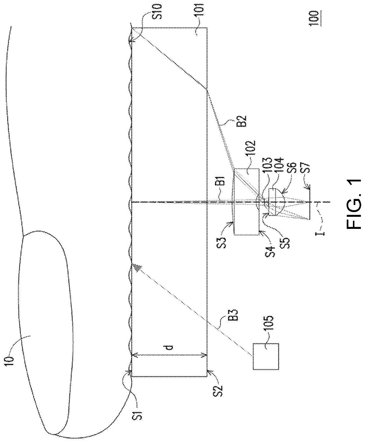
[0054]Detailed optical data of the first embodiment is shown in table one.

[0055]

TABLE ONEf = 0.312 mm, Fno = 2.64, HFOV = 60°, imgH = 0.402 mmradius offocalcurvaturedistancerefractivedispersionlengthsurface(mm)(mm)indexcoefficient(mm)tested object 10surface S100cover plate 101object sideinfinity1.8001.5264.2surface S1image sideinfinity0.600surface S2first lensobject side3.50830.5821.58529.9−0.51element 102surface S3image side2.02310.200surface S4aperture 103infinity0.100second lensobject side1.04760.3811.58529.90.38element 104surface S5image side−0.54960.600surface S6imaging planeimaging planeinfinityS7S7

In the table one:

f is an effective focal length (EFL) of the image capturing apparatus 100;

Fno is an f-number of the image capturing apparatus 100;

HFOV is a half field of view (HFOV) of the image capturing apparatus 100, i.e. a half of the FOV;

imgH is a maximum imaging height of the image capturing apparatus 100 (i.e. a half of a diagonal length of an effective photosensitive region...

second embodiment

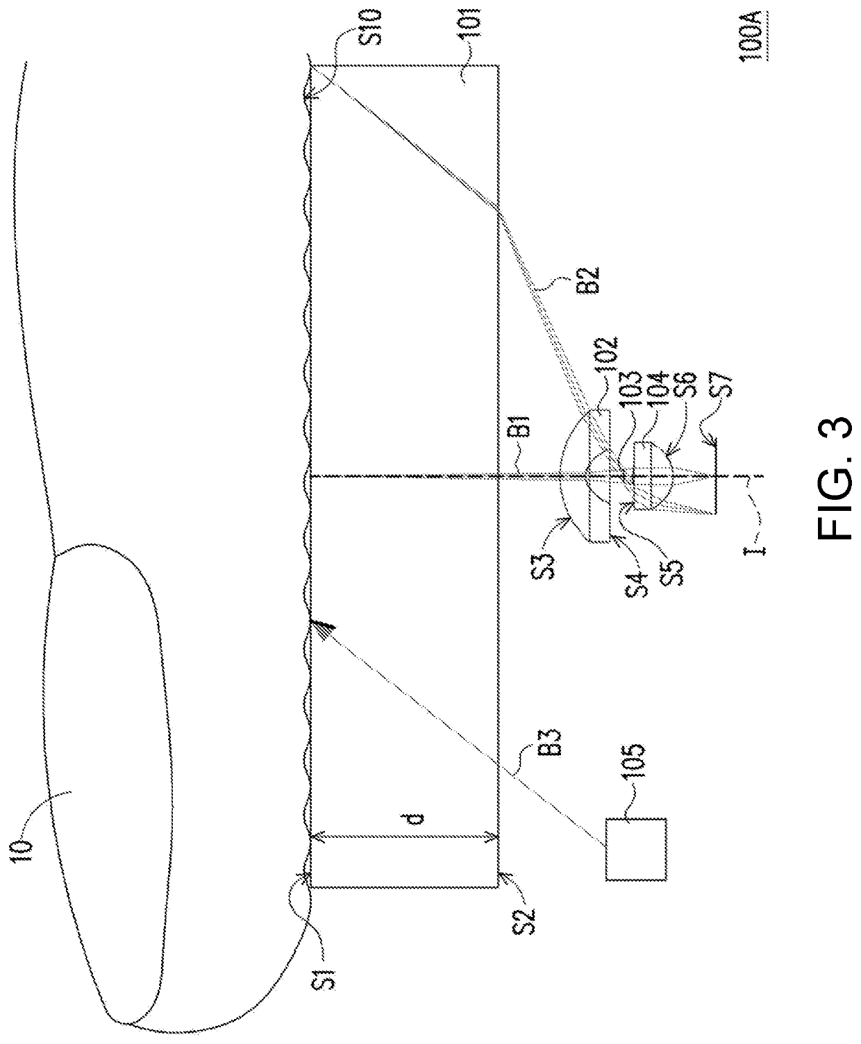
[0066]Detailed optical data of the second embodiment is shown in table four.

[0067]

TABLE FOURf = 0.179 mm, Fno = 2.58, HFOV = 60°, imgH = 0.358 mmradius offocalcurvaturedistancerefractivedispersionlengthsurface(mm)(mm)indexcoefficient(mm)tested object 10surface S100cover plate 101object sideinfinity1.8001.5264.2surface S1image sideinfinity0.600surface S2first lensobject side2.0800.251.58529.9−0.43element 102surface S3image side0.3270.364surface S4aperture 103infinity0.100second lensobject side0.8010.3811.67429.90.31element 104surface S5image side−0.5340.400surface S6imaging planeimaging planeinfinityS7S7

[0068]Various aspheric coefficients of the object side surfaces and the image side surfaces of the lens elements of the second embodiment in the equation (1) are as shown in table five.

[0069]

TABLE FIVElens elementfirst lens element 102second lens element 104surfaceobject sideimage sideobject sideimage sidesurface S3surface S4surface S5surface S6K9.3240.331−127.2370.637a20.3971.449−0.0...

third embodiment

[0074]Detailed optical data of the third embodiment is shown in table seven.

[0075]

TABLE SEVENf = 0.351 mm, Fno = 3.87, HFOV = 56°, imgH = 0.406 mmradius offocalcurvaturedistancerefractivedispersionlengthsurface(mm)(mm)indexcoefficient(mm)tested object 10surface S100cover plate 101object sideinfinity1.81.5264.2surface S1image sideinfinity0.6surface S2first lens elementobject side0.03820.351.58521.5−1.44102surface S3image side0.5270.5surface S4aperture 103infinity0.1second lensobject side0.1320.351.58521.50.43element 104surface S5image side−0.8650.502surface S6imaging plane S7imaging planeinfinityS7

[0076]Various aspheric coefficients of the object side surfaces and the image side surfaces of the lens elements of the third embodiment in the equation (1) are as shown in table eight.

[0077]

TABLE EIGHTlensfirst lens element 102second lens element 104surfaceobject sideimage sideobject sideimage sidesurface S3surface S4surface S5surface S6K−1.00−0.638−1.03614.904a2−12.9660.242−3.114−1.024a40...


PUM


Abstract

An image capturing apparatus including a cover plate, a first lens element and a second lens element arranged sequentially from an object side to an image side along an optical axis is provided. The number of lens elements in the image capturing apparatus is only two. The image capturing apparatus satisfies: 0.2<f / imgH<0.9, 2.9<N1+N2<3.7, and 2<(OTL−d) / imgH<8, wherein f is an effective focal length of the image capturing apparatus, imgH is a maximum imaging height of the image capturing apparatus, N1 is a refractive index of the first lens element, N2 is a refractive index of the second lens element, OTL is a distance from a tested object to an imaging plane on the optical axis, and d is a thickness of the cover plate.

Description

CROSS-REFERENCE TO RELATED APPLICATION[0001]This application claims the priority benefits of U.S. provisional application Ser. No. 62 / 691,631, filed on Jun. 29, 2018, and U.S. provisional application Ser. No. 62 / 728,079, filed on Sep. 7, 2018, and Taiwan application serial no. 107132958, filed on Sep. 19, 2018. The entirety of each of the above-mentioned patent applications is hereby incorporated by reference herein and made a part of this specification.BACKGROUNDTechnical Field[0002]The disclosure relates to an electronic device, and particularly relates to an image capturing apparatus.Description of Related Art[0003]Conventional electronic devices mainly use a capacitive sensing technology to implement biological feature recognition (such as fingerprint recognition, palm print recognition or vein recognition, etc.). Although the capacitive sensing technology has an advantage of small volume, its complicated circuit structure leads to manufacturing difficulty and high manufacturing...

Claims


Application Information

Patent Timeline
Patent Type & Authority Patents(United States)
IPC IPC(8): G06K9/00G07C9/37G02B27/09G06K9/20
CPCG06K9/2018G02B27/0955G07C9/37G07C2209/65G02B13/003G02B13/06G02B13/18G02B13/24G02B13/22G06V40/1324
Inventor CHIU, YI-FENGWANG, CHIUNG-HANWU, JEN-CHIEH
Owner GINGY TECH
Why Eureka
Eureka Blog
Learn More