Electric toothbrush

a technology of electric toothbrushes and swivels, which is applied in the field of electric toothbrushes, can solve the problems of unintentional disengagement, unintentional disengagement of the bayonet coupling, and limited axial securing achieved by the latching device, and achieve the effect of facilitating pin entry and facilitating pin pulling

Active Publication Date: 2020-12-22
BRAUN GMBH
View PDF22 Cites 7 Cited by
  • Summary
  • Abstract
  • Description
  • Claims
  • Application Information

AI Technical Summary

Benefits of technology

[0017]In one embodiment, the coupling pin extends in a direction substantially perpendicular to the longitudinal axis and / or a direction substantially perpendicular to the outer walls of the coupling stem. The coupling stem may beneficially include a rib oriented in the longitudinal axis and having a first (lower) end and a second (upper) end opposite to the first end. The rib can be disposed adjacent to the pin. In one embodiment, the pin is disposed between or intermediate the first end and the second end of the rib. The refill may comprise a groove structured and configured to engage the upper end of the rib of the coupling stem, to restrict axial movement of the refill relative to the handle when the refill is being axially attached to the handle.
[0019]The coupling surfaces are structured and configured to slidably and resiliently engage the coupling pin when the refill is being axially attached to the handle, i.e., when the refill is being axially moved relative to the handle and the pin arranged thereon. During attachment, the mutually opposite slide portions of the coupling surfaces slide downwardly in resilient contact with the pin. When the pin reaches the clamp portion, the pin is pulled into a snap fit with the coupling surfaces inside the clamp portion. To facilitate the pin's entry into the space between the two coupling surfaces, each of the slide portions may include a chamfer.
[0020]The slide portions of the first and second coupling surfaces can be arranged substantially parallel to the longitudinal axis (and hence parallel to one another). Alternatively, at least one of slide portions can be angled relative to the longitudinal axis. An included angle between the slide portions can be from about 0.1 degree to about 20 degrees, from about 1 degree to about 15 degrees, from about 1.5 degrees to about 10 degrees, and specifically from about 2 degrees to about 3 degrees. In one embodiment, each of the slide portions are symmetrically angled relative to the longitudinal axis such that the space between the mutually opposite slide surfaces increases upwardly, i.e., from the chamfers to the clamp portion. Such a configuration facilitates pulling of the pin into the clamp portion of the coupling surfaces, due to the resilience of the cantilevered arms and associated pressure of the coupling surfaces acting on the pin as the pin slides along the slide surfaces.

Problems solved by technology

Also, when the brush head is worn out and / or otherwise needs to be replaced, only a refill—as opposed to the entire electric toothbrush including the handle—needs to be replaced.
However, the additional axial securing achieved by this latching device is limited due to the outer circumference of the handle neck becoming dirty, for example with toothpaste residue and the like.
In addition, the neck of the toothbrush is sometimes grasped with the fingers, which can cause unintentional disengagement due to external pressure on the latching connection.
However, radial forces can cause unintentional disengagement of the bayonet coupling if these forces are applied in the correct (so to speak) direction of rotation relative to the handle, thus making additional securing measures necessary.
Instead, a drive shaft on the handle must be threaded into the toothbrush head, which can sometimes pose problems and requires a particular drive movement of the drive shaft.

Method used


Image

  • Electric toothbrush
  • Electric toothbrush
  • Electric toothbrush

Examples


Embodiment Construction

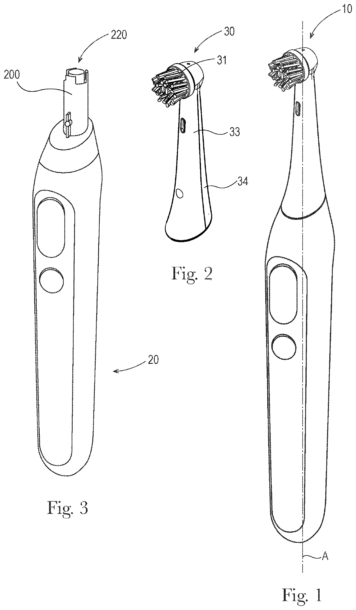
[0048]As is shown in FIGS. 1-3, an electric toothbrush 10 of the disclosure comprises a handle 20 and a refill 30 having a longitudinal axis or longitudinal direction A. In the embodiment of FIG. 1 the longitudinal axis A of the refill 30 coincides with that of the handle 20, but one skilled in the art will appreciate that in some embodiments (not shown here) the refill can be designed to be slightly angled relative to the handle, in which instances the longitudinal axis of the refill may not coincide with or be parallel to the that of the handle. Such an angled embodiment is included in the scope of the invention.

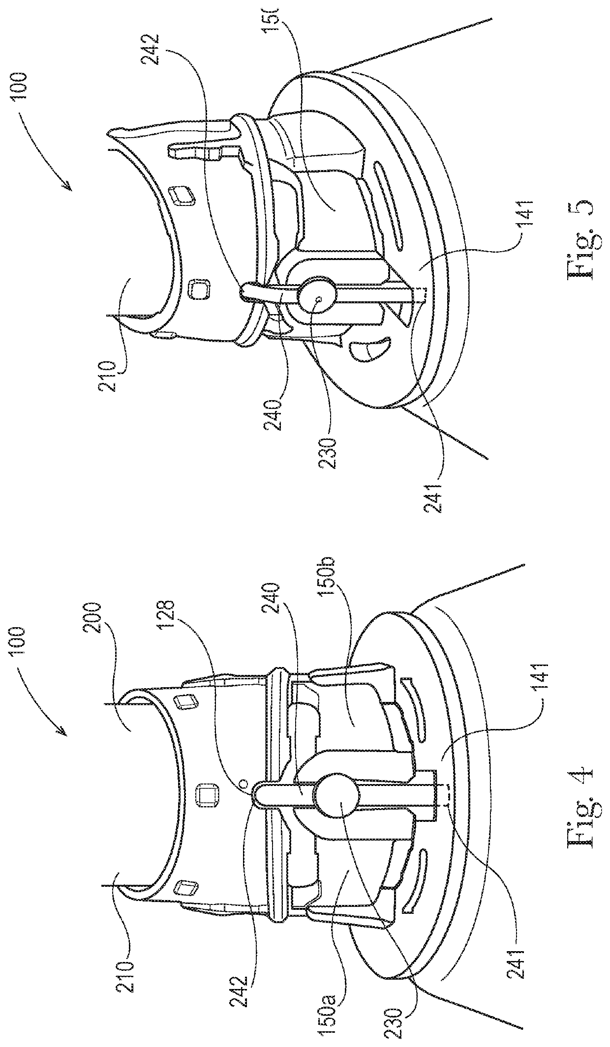
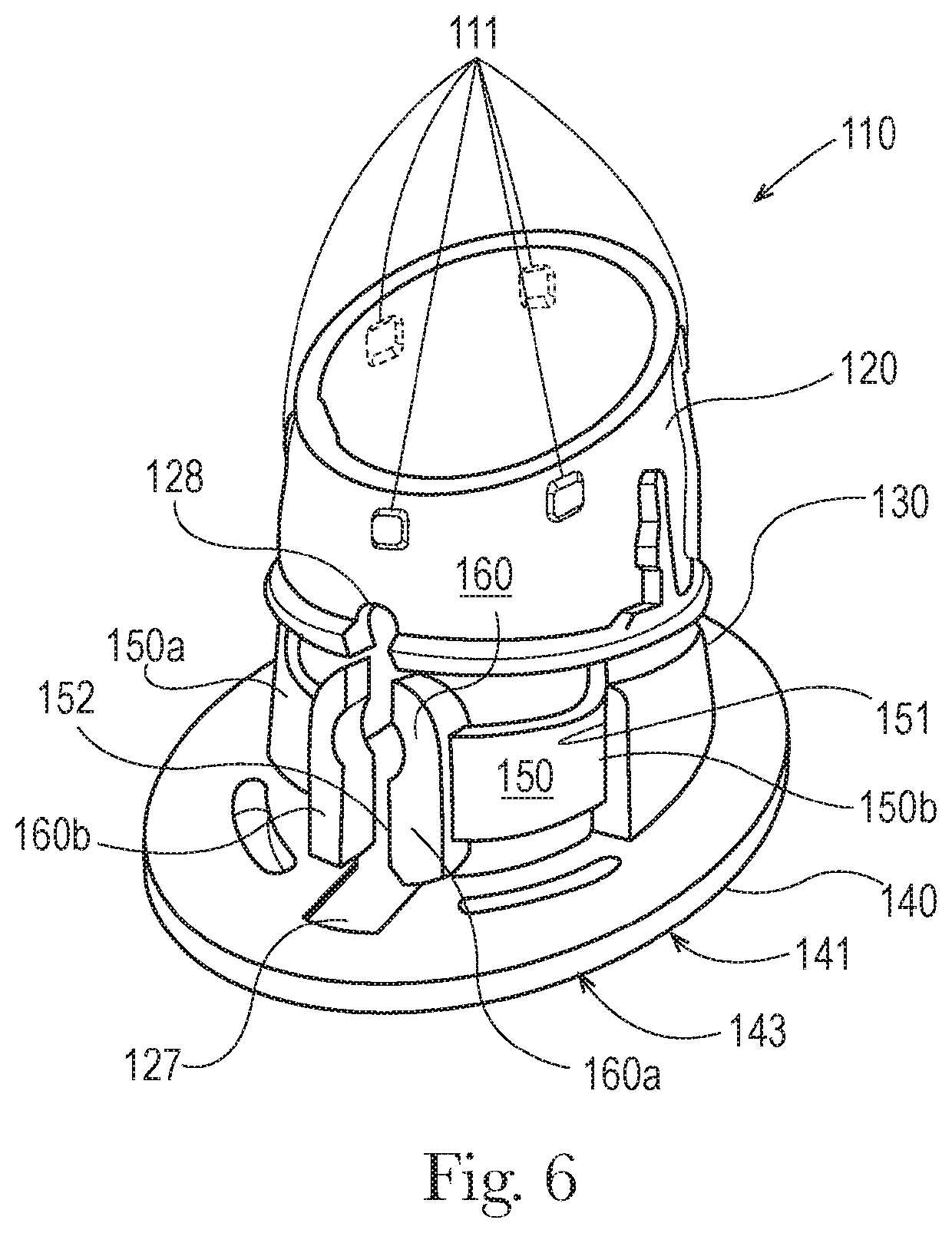
[0049]The refill 30 is structured and configured to be attached to the handle 20 via a coupling device 100, FIGS. 4-7. The handle 20 has a drive mechanism (not shown) inside, and the refill 30 has a brush head 31 and a motion transmitter 300 (FIG. 7) functionally connected to the brush head 31 for driving the brush head 31. The handle 20 further comprises a coupling stem 2...


PUM


Abstract

An electric toothbrush, including a refill connectable to a handle via a coupling device. The handle has a drive mechanism, and the refill has a brush head and a motion transmitter functionally connected to the brush head for driving it. The handle has a coupling stem terminating with a free end and including a coupling pin extending from the stem. The refill includes a generally tubular portion formed by refill walls defining an interior space for accepting the coupling stem of the handle. The coupling device comprises a pair of mutually opposite and resiliently deformable cantilevered arms disposed adjacent to the refill walls in the interior space of the refill. Each of the cantilevered arms terminates with a coupling surface for engaging the stem's coupling pin for secure and disengageable connection between the handle and the refill.

Description

CROSS REFERENCE TO RELATED APPLICATION[0001]This application claims the benefit of U.S. Provisional Application No. 62 / 525,660 filed Jun. 27, 2017, the entire contents of which are incorporated by reference.FIELD OF THE INVENTION[0002]The present disclosure is directed to an electric toothbrush, and more particularly to a coupling arrangement between the toothbrush's handle and an attachment part, or refill, wherein the refill having a functional brush head is connected to a toothbrush handle comprising a drive shaft for driving the brush head.BACKGROUND[0003]Electric toothbrushes generally have removable and exchangeable attachment brushes, also known as “refills,” so that a common handle can be used by multiple family members, each family member having a separate personal refill. Also, when the brush head is worn out and / or otherwise needs to be replaced, only a refill—as opposed to the entire electric toothbrush including the handle—needs to be replaced.[0004]During brushing, var...

Claims


Application Information

Patent Timeline
Patent Type & Authority Patents(United States)
IPC IPC(8): A61C17/22A61C17/34
CPCA61C17/3436A61C17/222A46B7/04A46B9/04A46B13/008
Inventor FRITSCH, THOMASNEUSSER, IRINAUTSCH, JOERN
Owner BRAUN GMBH
Why Eureka
Try Eureka