Method for charging electric vehicles

a charging method and electric vehicle technology, applied in the direction of charging stations, battery/fuel cell control arrangements, transportation and packaging, etc., can solve the problems of increasing the time required to complete charging, and achieve the effects of improving charging efficiency, improving customer convenience, and improving charging efficiency

Active Publication Date: 2020-12-22
HYUNDAI MOTOR CO LTD +1
View PDF20 Cites 1 Cited by
  • Summary
  • Abstract
  • Description
  • Claims
  • Application Information

AI Technical Summary

Benefits of technology

[0006]More specifically, the present disclosure provides a method for charging electric vehicles to alleviate a charging speed decrease according to the charge amount of a normal lithium-ion battery and to improve power supply effect using available power.
[0011]According to an embodiment, the method may further include switching the inlet used for charging from one inlet to two or more inlets when the number of inlets used for charging is changed. Thus, charging efficiency of the high-voltage battery unit decreases.
[0021]According to an embodiment, the second controller may switch the inlets used for charging from one inlet to two or more inlets when the number of inlets used for charging is changed. Thus, charging efficiency of the high-voltage battery unit decreases.
[0027]The method of charging electric vehicles according to the present disclosure has the following effects.
[0028]First, after switching from charging using two inlets to charging using one inlet, an air-conditioner or a heater is operated using a 1-inlet charger, which stops charging, improving charging efficiency. In addition, user convenience application components such as a bedroom, heating / cooling cabinets, and a 220V inverter, can perform functions such as air-conditioning, charging, or other operations using power supplied from an external charger during charging of an electric vehicle, improving charging efficiency.
[0030]Third, when charging is performed while the inside of a bus is cooled, a time required to complete charging increases due to battery consumption caused by an air-conditioning operation (charging and air-conditioner on). However, the proposed algorithm can provide additional power without increasing a time required to complete charging.

Problems solved by technology

Third, when charging is performed while the inside of a bus is cooled, a time required to complete charging increases due to battery consumption caused by an air-conditioning operation (charging and air-conditioner on).

Method used


Image

  • Method for charging electric vehicles
  • Method for charging electric vehicles
  • Method for charging electric vehicles

Examples


first embodiment

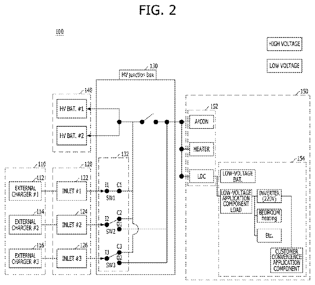
[0047]FIG. 2 illustrates a vehicle according to the present disclosure.

[0048]Referring to FIG. 2, two or more inlets may be used to charge a high-voltage battery unit according to the first embodiment.

[0049]A vehicle 100 may include an external charger 110, inlets 120, a high-voltage junction box 130, a high-voltage battery unit 140 and an application component 150. Hereinafter, the high-voltage junction box 130 is referred to as a “junction box 130”.

[0050]The vehicle 100 may include a plurality of external chargers 110. The plurality of external charges 110 may be respectively connected to a plurality of inlets 120.

[0051]For example, a first external charger 112 may be connected to a first inlet 122. Then, the first external charger 112 can provide a charging voltage and current to the junction box 130 through the first inlet 122.

[0052]A second external charger 114 may be connected to a second inlet 124. Then, the second external charger 114 can provide a charging voltage and curre...

second embodiment

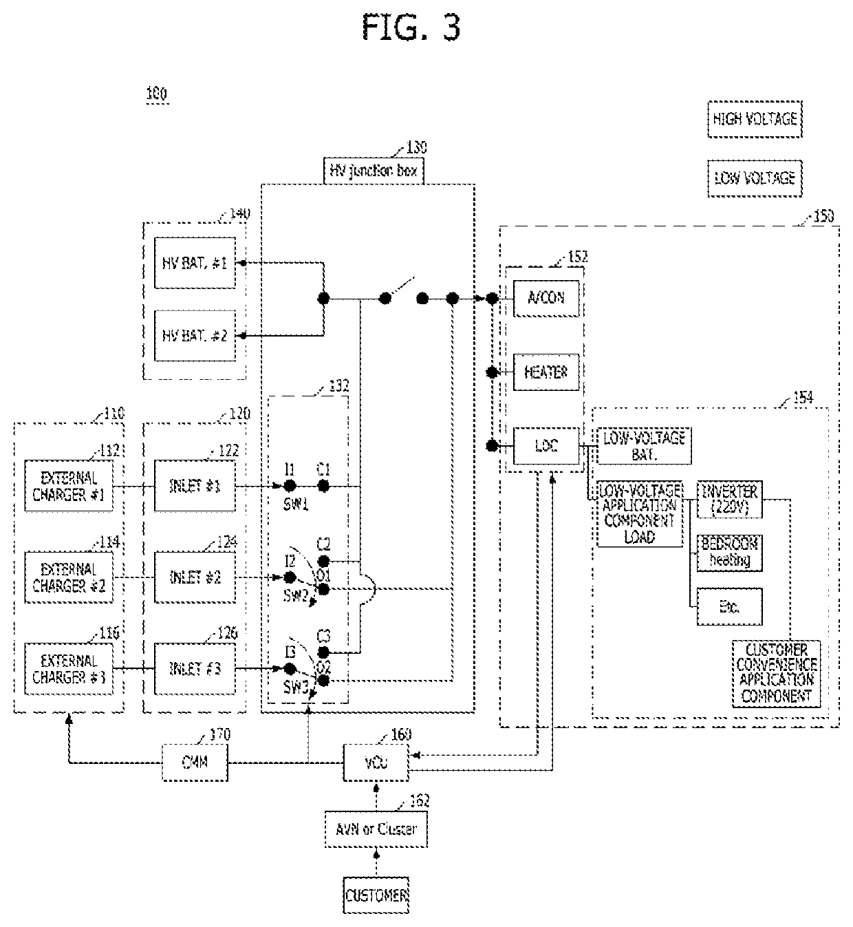
[0061]FIG. 3 illustrates a vehicle 100 according to the present disclosure.

[0062]The second embodiment illustrates a circuit where two or more inlets change to one inlet 120. In this embodiment, power supplied through the first inlet 122 may be used to charge the high-voltage battery unit 140. Power supplied through the second and third inlets may be used as available power.

[0063]Referring to FIG. 3, the vehicle 100 may include the external charger 110, the inlets 120, the junction box 130, the high-voltage battery unit 140, the application component 150, a vehicle control unit (VCU) 160, and a chassis management module (CMM) 170. The CMM 170 may be a first controller for a method of charging electric vehicles. The VCU may be a second controller for the method of charging electric vehicles.

[0064]The VCU 160 may receive the charge amount of the high-voltage battery unit 140. When the charge amount of the high-voltage battery unit 140 reaches a saturation level, the charging speed and...

third embodiment

[0090]FIG. 5 is a vehicle according to the present disclosure.

[0091]Referring to FIG. 5, the third embodiment illustrates a circuit where two or more inlets 120 switch to one inlet 120. In this embodiment, the first inlet 122 may be used to charge the high-voltage battery unit 140. The second inlet 124 and the third inlet 126 may be used to operate an application component with priority using available power.

[0092]Referring to FIG. 5, the vehicle 100 may include the external charger 110, the inlets120, the junction box 130, the high-voltage battery unit 140, the application component 150, the vehicle control unit (VCU) 160, and the chassis management module (CMM) 170.

[0093]The VCU 160 may switch two or more inlets 120 to one inlet based on charging characteristics such as charging current, charging speed and a time required to complete charging according to the charge amount of the high-voltage battery unit 140 and a prestored lookup table.

[0094]In addition, when charging efficiency...


PUM


Abstract

A method of charging electric vehicles includes charging a high-voltage battery unit with power supplied through two or more inlets. The method includes determining whether the charge amount of the high-voltage battery unit has reached a predetermined charge amount. The method includes charging the high-voltage battery unit with power supplied through one of the two or more inlets and controlling a first switching unit such that power supplied through the remaining inlets is provided to an application component when the charge amount of the high-voltage battery unit has reached the predetermined charge amount.

Description

[0001]This application claims priority to and the benefit of Korean Patent Application No. 10-2018-0104499, filed on Sep. 3, 2018, which is hereby incorporated by reference as if fully set forth herein.BACKGROUNDField of the Disclosure[0002]The present disclosure relates to a method for charging electric vehicles.Discussion of the Related Art[0003]With increasing demand for electric vehicles, charging methods for improving charging efficiency are becoming increasingly important. High-voltage (HV) battery capacity currently applied to electric buses is about 256 kWh, which is larger than the battery capacity of normal electric cars. Accordingly, quick charging and charging using two inlets are applied in order to reduce the charging time of a large-capacity high-voltage battery. Quick charging power of electric buses is about 850V and 200 A when COMBO type 2 is used. Further, double deck electric buses require a high-voltage battery with battery capacity of 384 kWh and a charging met...

Claims


Application Information

Patent Timeline
Patent Type & Authority Patents(United States)
IPC IPC(8): H02J7/00B60L53/30B60L53/14
CPCB60L53/14B60L53/30B60Y2300/91B60Y2200/91B60L53/67B60L58/13B60L1/00B60L2240/529B60L2240/527Y02T10/70Y02T10/7072Y02T90/14Y02T90/12B60L58/10B60L53/16B60L53/665B60R16/0239B60L2240/547
Inventor KIM, SEUNG WOO
Owner HYUNDAI MOTOR CO LTD
Why Eureka
Try Eureka