
Floating debris remover

a technology of floating debris and remover, which is applied in water cleaning, special-purpose vessels, vessel parts, etc., can solve the problems of unsightly and difficult to navigate lakes, unwanted spread of harmful invasive weeds, unsightly and polluting debris,

Active Publication Date: 2020-12-22
NICKELSON DAVID
View PDF9 Cites 1 Cited by
  • Summary
  • Abstract
  • Description
  • Claims
  • Application Information

AI Technical Summary

Problems solved by technology

One of the problems encountered with lakes or other bodies of water is that both weeds, which grow naturally in a lake, and debris, which typically accumulates around boat docks from either storms or human activity, makes the lake unsightly as well as difficult to navigate.
In some cases the debris may be a harmful invasive weed species that needs to be contained and removed from the lake since the weeds can be accidently transported from lake to lake by an unsuspecting boater, which results in unwanted spread of the harmful invasive weed.
Other types of debris may be the result of human activity or storm damage.
The debris problem occurs in marinas with multiple docks or in water areas where there is an isolated dock, however, in either case one needs an efficient way to remove the unsightly and polluting debris from the lake.
The task can be time consuming, as the debris must either be removed by hand or with bulky machines.

Method used


Image

  • Floating debris remover
  • Floating debris remover
  • Floating debris remover

Examples


Embodiment Construction

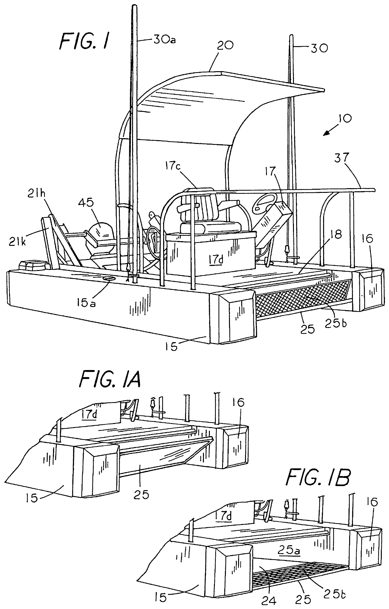
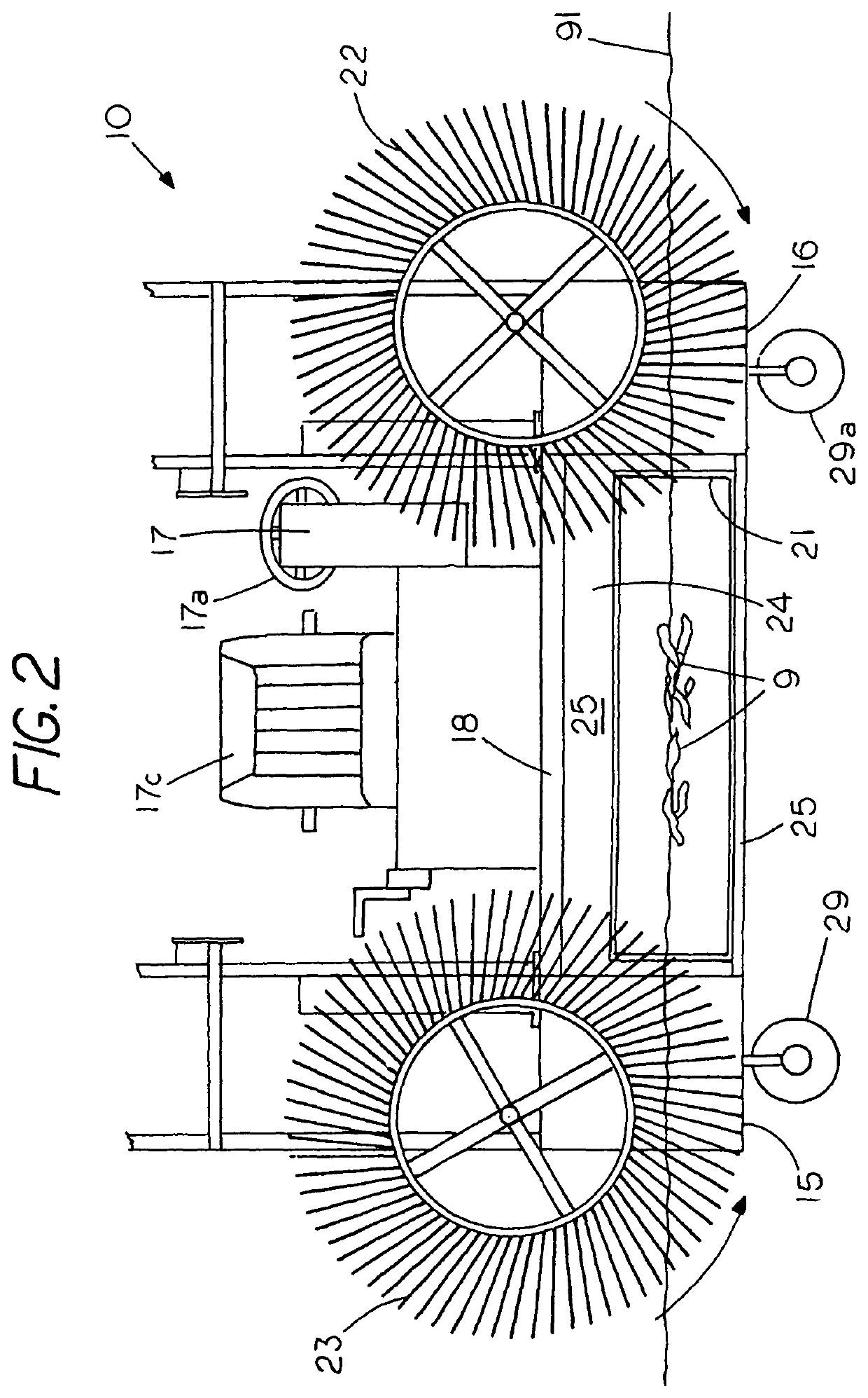
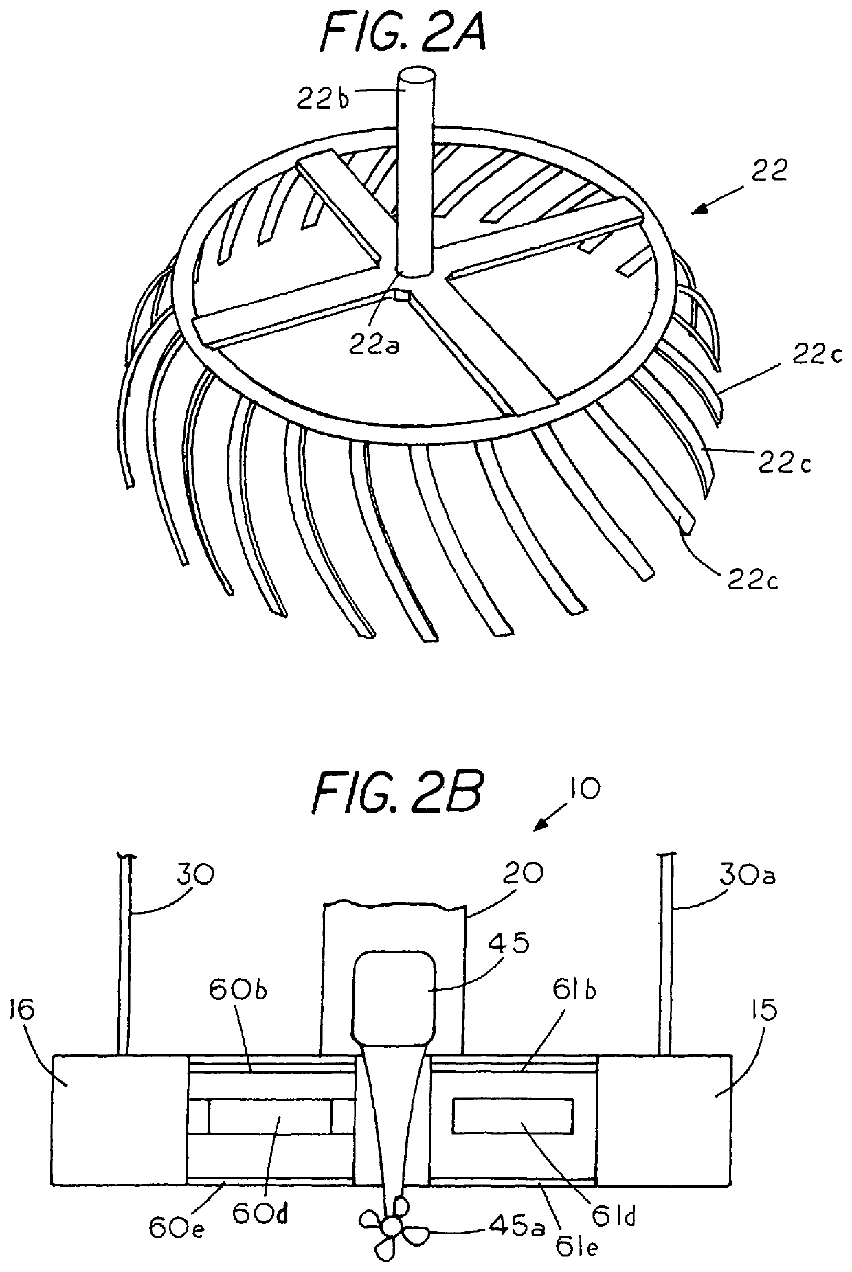
[0030]FIG. 1 is a perspective view of an operator driven, floating debris remover 10 with a deck 18 supported by a pair of pontoons 15, 16 with the floating debris remover having a control station 17, a handrail 37, a storage container 17d, an operator seat 17c, a canopy 20 and an outboard motor 45. A manipulateable flow through debris scoop 21, which is located between outer pontoons 15 and 16 and in the rear of the debris remover 10, is shown in an isolated view in FIG. 3. The debris scoop is operator manipulateable through a set of pivot arms 21k and 21h and pivot arms 21f and 21g (FIG. 3), which are typically operator controlled through a first power cylinder 21r and a second power cylinder 21s, which may be hydraulic cylinders or the like. That is, the debris remover 10 lift arm 21f and lift arm 21h elevates the tiltable screen bucket or tiltable scoop 21 from a debris harvesting position between the set of pontoons (FIG. 2) to a debris emptying condition proximate a refuse con...


PUM


Abstract

A floating debris remover having an operator station for directing debris into a debris inlet and a power manipulateable debris scoop for on-the-go separation of the debris from the water through elevation of the debris scoop with the debris remover having an operator station to allow an onboard operator to retrieve and deposit debris at a waste disposal site solely through operator manipulation of the debris scoop.

Description

CROSS REFERENCE TO RELATED APPLICATIONS[0001]This application is a continuation application of U.S. application Ser. No. 15 / 731,513 filed Jun. 21, 2017 (pending), which claims priority from provisional application Ser. 62 / 493,182 filed Jun. 24, 2016 and provisional application Ser. 62 / 495,845 filed Sep. 26, 2016.STATEMENT REGARDING FEDERALLY SPONSORED RESEARCH OR DEVELOPMENT[0002]NoneREFERENCE TO A MICROFICHE APPENDIX[0003]NoneBACKGROUND OF THE INVENTION[0004]One of the problems encountered with lakes or other bodies of water is that both weeds, which grow naturally in a lake, and debris, which typically accumulates around boat docks from either storms or human activity, makes the lake unsightly as well as difficult to navigate. In some cases the debris may be a harmful invasive weed species that needs to be contained and removed from the lake since the weeds can be accidently transported from lake to lake by an unsuspecting boater, which results in unwanted spread of the harmful in...

Claims


Application Information

Patent Timeline
Patent Type & Authority Patents(United States)
IPC IPC(8): E02B15/04E02B15/10B63B35/32B63B21/26B63B35/34B63H20/00
CPCE02B15/10B63B35/32E02B15/046E02B15/106B63B35/34B63H2020/003B63B21/26B63B1/121
Inventor NICKELSON, DAVID
Owner NICKELSON DAVID
Learn More