Threaded joint for coupling rods

a technology of threaded joints and rods, which is applied in the direction of screw threaded joints, pipes/joints/fittings, mechanical equipment, etc., can solve the problems of increasing the tension of the drill string, increasing the wear of the joints, and imposing an axial load on the joints, so as to prevent galling

Active Publication Date: 2020-12-29
DIVERSITY TECH CORP
View PDF20 Cites 0 Cited by
  • Summary
  • Abstract
  • Description
  • Claims
  • Application Information

AI Technical Summary

Benefits of technology

[0022]The secondary geometries of the box and pin threads provide constant geometric profiles oriented along respective tapers at the ends of the tube. This geometric thread profile varies between the box and pin threads in terms of thread depth, deburred depth (the depth of the chamfer or radius that is provided between the respective flanks and the crests of each thread) and taper angle, although these features are constant for the given end (i.e. the box thread depth remains constant along its tapered helical path but differs from the pin thread depth). The presence of arcuate chamfer and radius surfaces (i.e. curved convex and concave surfaces) as described herein prevents galling or other undesirable effects from occurring in use. The box and pin thread geometries oriented between frusto-conical surfaces are such that a portion (but not the entirety) of the pin thread crest and box thread root are in contact when threaded and a portion thereof is out of contact, wherein an interference fit results when threaded together. In this configuration, the box thread crest and pin thread root make no contact when threaded together and contain a frusto-conical radial gap. The pressure flanks on both the box and pin threads are oriented at an angle which is normal to the taper of the thread (i.e. the conical surfaces defined by the crest and root surfaces) allowing forces to be transferred in an efficient manner (in some cases up to 99.98% of the force component is axial). The clearance flanks on both the box and pin threads are oriented at about 45° to the taper of the thread, allowing the threads to withstand damage from stabbing during thread make-up.

Problems solved by technology

This increases tension on the drill string and imposes an axial load on the joints.
Also, cuttings are continually being flushed from the drill bit to the collar at the drill rig, between the OD of the drill string and the bore hole ID, so any belling outwards of the box thread OD can compromise this flow, creating potential problems.
Increased wear could also result from OD belling of the joint.

Method used


Image

  • Threaded joint for coupling rods
  • Threaded joint for coupling rods
  • Threaded joint for coupling rods

Examples


Embodiment Construction

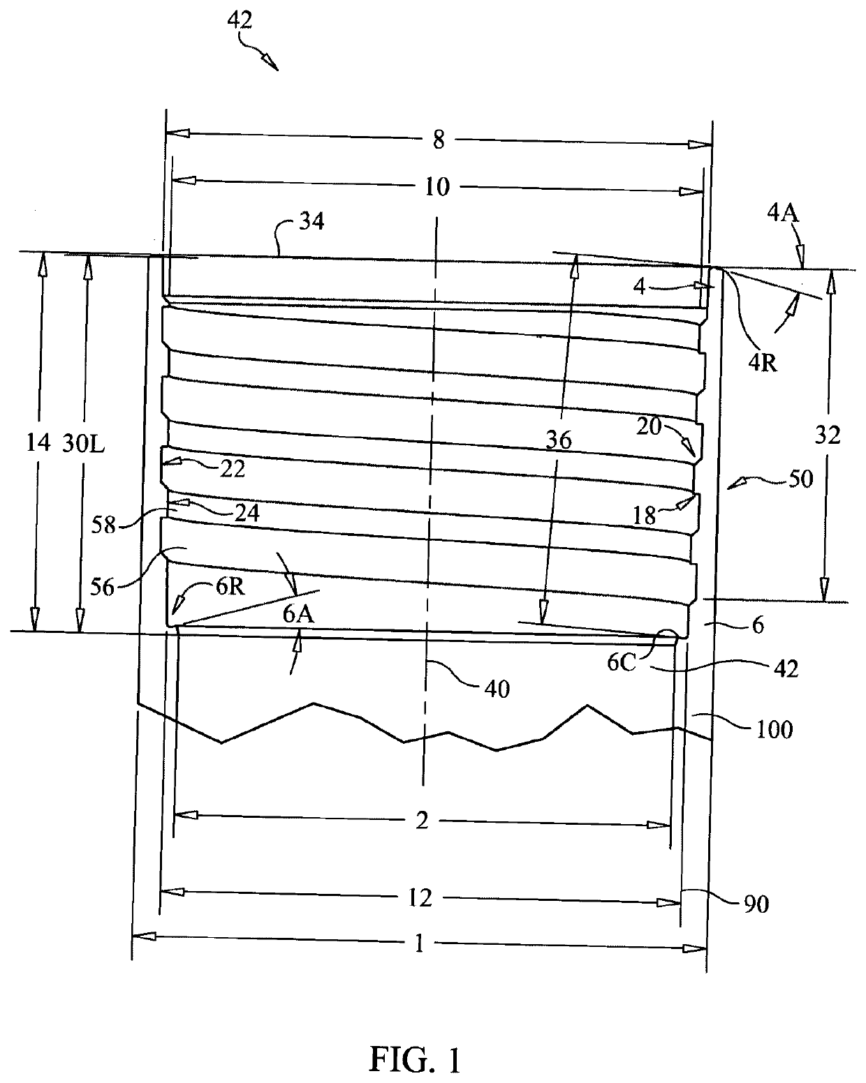
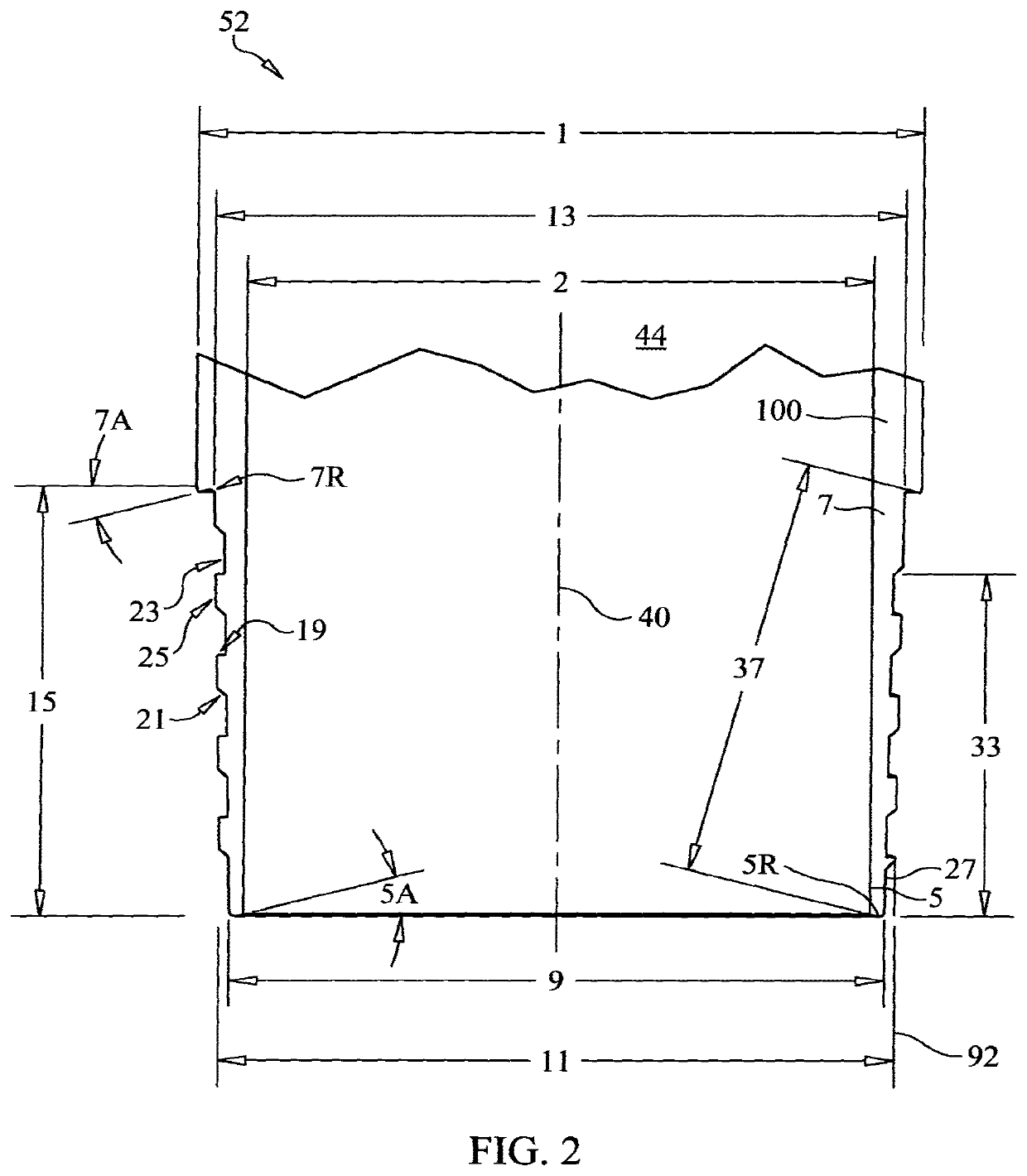
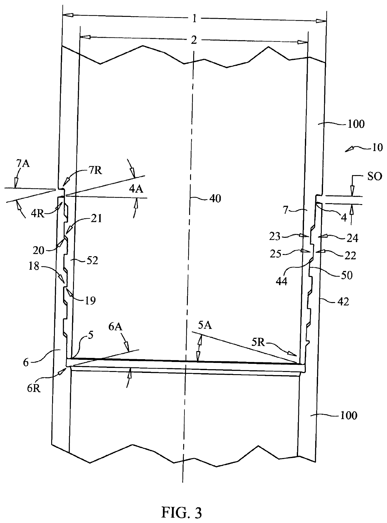
[0045]Referring to the figures and in particular FIG. 3, a threaded joint 10 according to one embodiment of the invention comprises mutually engaging box and pin threads 50 and 52 provided on respective ends of tubes 100, which may comprise for example drill rods or casings. It will be seen that the invention may be adapted for coupling together various types of rods, tubes or the like having a variety of industrial applications. Tubes 100 have opposing end regions 42 and 44 with a central (primary) axis 40 extending between the ends. A first end region 42, seen in FIG. 1, is provided with box thread 50 and the opposed end region 44 seen in FIG. 2 is provided with pin thread 52. For convenience, both of the box and pin threads described herein are considered to share axis 40 as their respective central axes, although it will be seen that tube 100 need not be linear. However, for convenience of description it will be assumed for purpose of this embodiment that tube 100 is linear.

[004...


PUM


Abstract

The application relates to a threaded cylindrical member, which may be used for a segmented drilling tube. The member has opposing first and second ends and a central axis between the ends. The first end is threaded with a pin thread including a pressure flank, a crest and a root. The second end is threaded with a box thread including a pressure flank, a root, wherein the pin and box threads are configured whereby when threaded together a portion of the root of the pin thread is out of contact with the crest of the box thread to leave gap therebetween. The secondary geometries of the pin and box threads are configured to generate an interference fit between the pin and box threads. The roots and crests of the pin and box threads define parallel tapering conical frustrums that differ from each other in their taper angles.

Description

FIELD OF THE INVENTION[0001]This invention pertains to threaded tubes and rods such as tubes and casings used for subsurface drilling. The invention relates in particular to threaded joints for coupling together segmented tubes and rods such as thin wall threaded drill rods and casings used in surface and underground drilling in the mineral exploration industry using diamond core drill bits, as well as other applications.BACKGROUND OF THE INVENTION[0002]A drill string is typically composed of a large number of drill rods or casings which are threaded together incrementally as the drilling progresses. The joints of the drill string serve to transfer torque to the core barrel and diamond drill bit, allowing the drill string to machine its way through the formation as the upper end is rotated. As the drill string increases in length, the total drill string weight will in time exceed the required axial (downward) drilling force and an opposite ‘pullback force’ is required to maintain th...

Claims


Application Information

Patent Timeline
Patent Type & Authority Patents(United States)
IPC IPC(8): E21B17/042F16L15/00F16L15/06
CPCF16L15/002F16L15/06E21B17/042E21B17/0423
Inventor GUSHULAK, RICHIE
Owner DIVERSITY TECH CORP
Why Eureka
Try Eureka