Real time HUMS

a real-time hum and data analysis technology, applied in the field of real-time hums, can solve the problems of insufficient information to take appropriate remedial action, and the data cannot be analyzed between flights

Active Publication Date: 2020-12-29
SIKORSKY AIRCRAFT CORP
View PDF30 Cites 1 Cited by
  • Summary
  • Abstract
  • Description
  • Claims
  • Application Information

AI Technical Summary

Problems solved by technology

One drawback of this process is that the HUMS data can only be analyzed between flights, i.e., once the aircraft is on the ground.
Therefore, if a hazardous condition arises during a flight, the pilot or crew, while they may be alerted to the hazardous condition, may not have enough information to take appropriate remedial action in-flight.

Method used


Image

  • Real time HUMS
  • Real time HUMS
  • Real time HUMS

Examples


Embodiment Construction

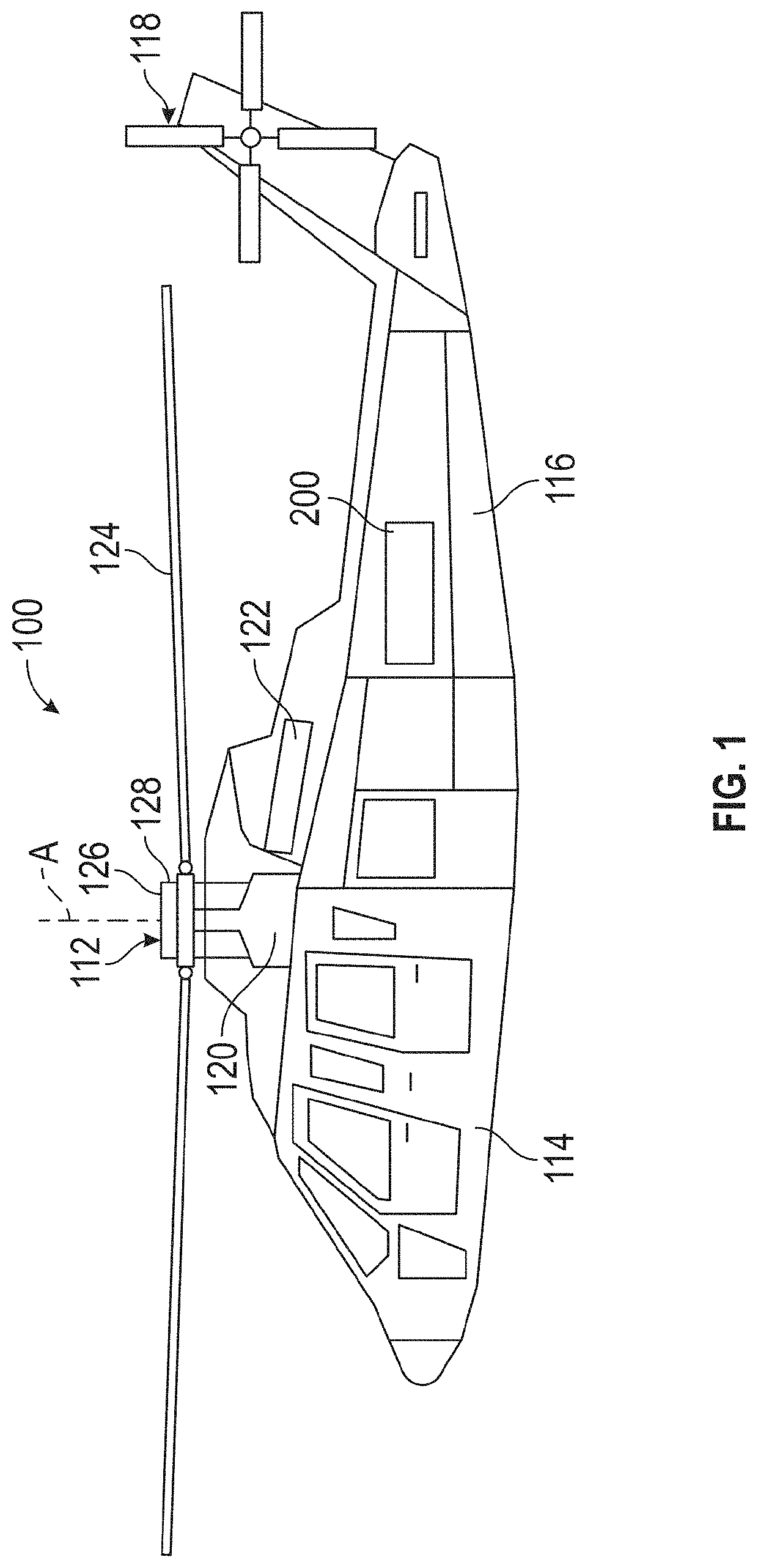
[0012]Referring now to the Figures, where the invention will be described with reference to specific embodiments, without limiting same, FIG. 1 schematically illustrates a conventional rotary wing aircraft 100 having a main rotor assembly 112 and which includes a real time health and usage management system (RT HUMS). The aircraft 100 includes an airframe 114 having an extending tail 116 which mounts an anti-torque system, such as a tail rotor assembly 118. The main rotor assembly 112 is driven about an axis of rotation A through a transmission (illustrated schematically at 120) by one or more engines 122. The main rotor assembly 112 includes a plurality of rotor blades 124 mounted to a rotor hub 126, and a swashplate 128 that is used to affect a state or orientation of the rotor blades 124. The rotor blades 124 can have a variable pitch that can be used to affect pitch and roll angles of the aircraft 100 as well as velocity of the aircraft 100. The pitch of the rotor blades 124 can...


PUM


Abstract

A system and method for operating an aircraft. The system includes a health and usage monitoring system (HUMS) system for sensing health and usage data during flight of the aircraft, and a data transmission unit. The data transmission unit retrieves HUMS data from the HUMS system and generates a trigger signal when the retrieved HUMS data meets a selected criterion, the trigger signal being indicative of a condition of the aircraft. In response to the trigger signal, the data transmission unit transmits the retrieved HUMS data to a remote location.

Description

CROSS REFERENCE TO RELATED APPLICATIONS[0001]The present application claims priority from U.S. Provisional Application Ser. No. 62 / 487,137, filed on Apr. 19, 2017, the contents of which are incorporated herein by reference in their entirety.BACKGROUND OF THE INVENTION[0002]The present invention is directed to a system and method of monitoring the health of an aircraft and aircraft components and, in particular, to providing an analysis of health and usage monitoring system (HUMS) data for analysis during flight of the aircraft.[0003]Aircraft are often equipped with a health and usage monitoring system (HUMS) to help ensure the maintenance and safe operation of the aircraft. During flight, the HUMS collects data with respect to various components of the aircraft, such as the engine, gearbox, rotors, etc. The HUMS data includes parameters such as engine torque, gearbox temperature, gearbox vibration, air speed, etc. The HUMS data is collected in-flight and stored at a memory device lo...

Claims


Application Information

Patent Timeline
Patent Type & Authority Patents(United States)
IPC IPC(8): G07C5/08G07C5/00B64D45/00B64F5/60B64F5/40B64C27/06
CPCG07C5/085G07C5/008B64D45/00B64F5/40B64C27/06B64D2045/008B64F5/60B64D2045/0085
Inventor CIABURRI, DANIEL A.ROZAK, JAMES N.
Owner SIKORSKY AIRCRAFT CORP
Why Eureka
Try Eureka