Aircraft landing gear assembly including a health and usage monitoring system (HUMS) and method

a technology for landing gear and health and usage monitoring, which is applied in the direction of aircraft components, aircraft health monitoring devices, and landing gear, etc., can solve problems such as aero-acoustic noise, and achieve the effect of removing or adversely affecting the intended load bearing capacity

Active Publication Date: 2020-12-08
MESSIER DOWTY
View PDF23 Cites 0 Cited by
  • Summary
  • Abstract
  • Description
  • Claims
  • Application Information

AI Technical Summary

Benefits of technology

[0014]Thus, the landing gear assembly according to the first aspect of the invention includes HUMS components housed within a cavity defined by a structural subassembly of the landing gear assembly. The structural subassembly also defines an opening or port which can be used by a maintenance engineer to access the cavity while the aircraft is stationary with weight on wheels. The access port can be closed by a removable cover so that during flight the port is substantially closed, although the cavity can be exposed to ambient conditions. The structural subassembly can serve as a protective casing for the HUMS to protect it from foreign object damage, avoiding the need for a dedicated casing. The structural subassembly can also substantially isolate the HUMS from incident airflow, which could lead to aero-acoustic noise if the HUMS components were mounted externally on the landing gear assembly. The landing gear assembly according to the first aspect can enable HUMS components to be readily installed and replaced via the opening during maintenance operations as line replaceable units.
[0016]The first subassembly can comprise metal, such as aluminium, steel, titanium or a suitable alloy. In such embodiments, the metal chamber walls can provide an electromagnetic interference (EMI) shield around the HUMS components, so as to shield other electronic aircraft systems from EMI generated by the HUMS components. This can lead to a landing gear assembly of reduced weight in view of the fact that it is not a requirement to provide a dedicated EMI shield.
[0027]Thus, the method according to the third aspect enables a landing gear assembly to be fitted with an HUMS at the point of manufacture, or retrofitted with an HUMS during a maintenance operation or during routine check operations.

Problems solved by technology

The structural subassembly can also substantially isolate the HUMS from incident airflow, which could lead to aero-acoustic noise if the HUMS components were mounted externally on the landing gear assembly.

Method used


Image

  • Aircraft landing gear assembly including a health and usage monitoring system (HUMS) and method
  • Aircraft landing gear assembly including a health and usage monitoring system (HUMS) and method
  • Aircraft landing gear assembly including a health and usage monitoring system (HUMS) and method

Examples


Embodiment Construction

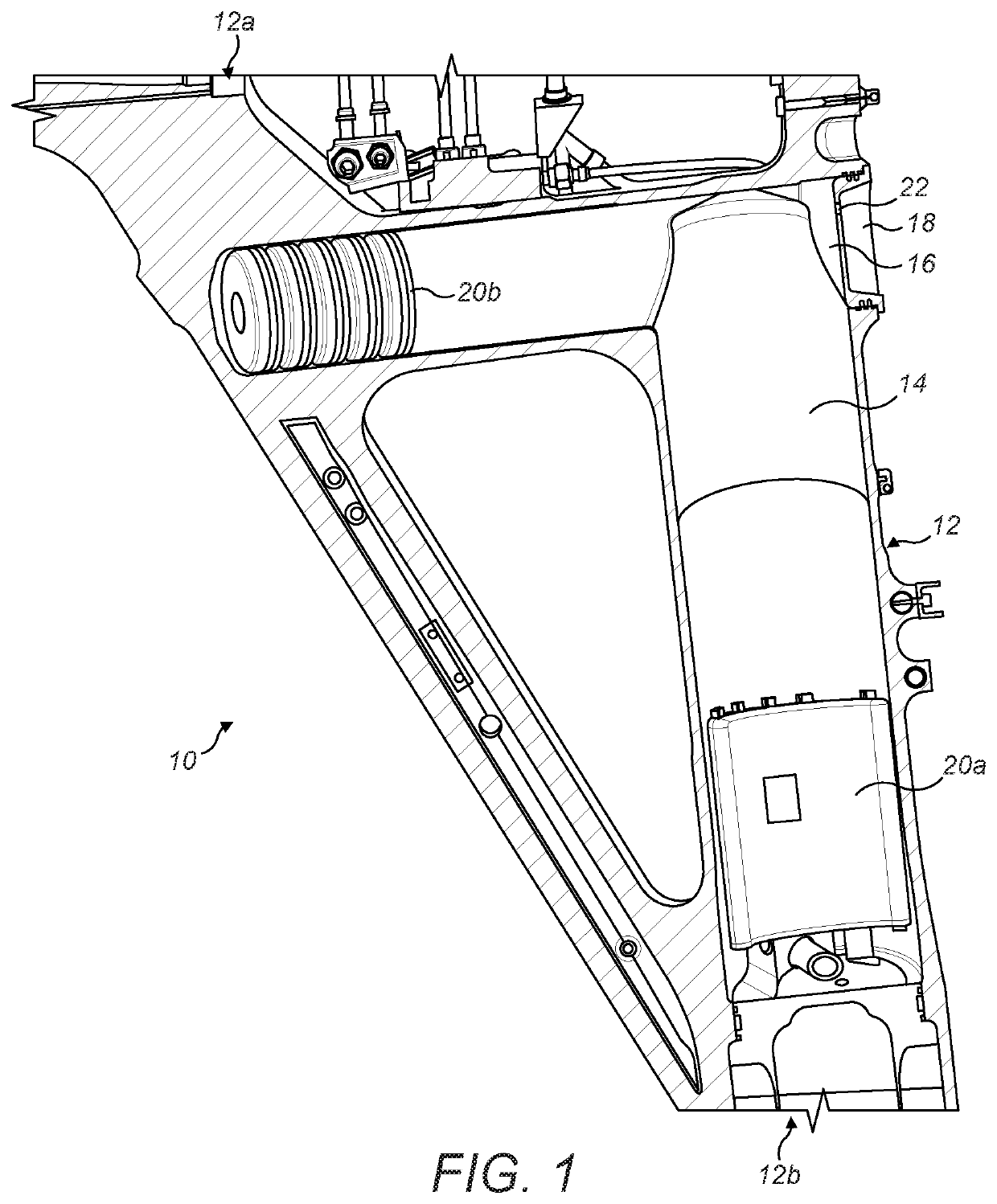
[0035]FIG. 1 shows an aircraft landing gear assembly 10 according to embodiment of the invention.

[0036]The landing gear assembly 10 includes a first structural subassembly, namely a main fitting 12 of a main shock absorbing strut. As will be appreciated, the main fitting 12 is intended to be movably coupled to an aircraft (not shown) such that the landing gear assembly 10 can be moved between a deployed condition for take-off and landing, and stowed condition for flight. An upper portion 12a is arranged to be pivotally coupled to the airframe. A lower portion 12b includes or defines a telescopic shock absorber. However, in some embodiments the landing gear assembly can include a rigid strut which does not include shock absorbing means.

[0037]The main fitting 12 defines an internal space or cavity 14 at an upper region of it. The cavity 14 is generally cylindrical in cross section and arranged in an inverted ‘L’ shape, with a longitudinal portion in communication with a lateral portio...


PUM


Abstract

A health and monitoring system or “HUMS” mounted within a hollow structural subassembly of an aircraft landing gear assembly, the subassembly having an access port for access to the HUMS without requiring disassembly of the structural subassembly so as to require jacking up the aircraft.

Description

[0001]This application claims the benefit of and priority to European Application 15191342.3, filed Oct. 23, 2015, the contents of which are incorporated herein by reference.BACKGROUND OF THE INVENTION[0002]It is known to provide an aircraft with a health and usage monitoring system (HUMS). A HUMS can include one or more sensors arranged to monitor parts of the aircraft to determine for example whether the parts have been subjected to mechanical loads exceeding a predetermined acceptable limit.[0003]One type of HUMS is known as an integrated vehicle health monitoring system (IVHMS), also known as an aircraft condition monitoring system (ACMS). An IVHMS is an integral part of an aircraft which is installed at the point of aircraft manufacture.[0004]It is also known to provide a HUMS upgrade which can be retrofitted to an in-service aircraft by interfacing the HUMS with the aircraft's IVHMS and / or avionics system.[0005]The present inventor has identified that HUMS can be improved in t...

Claims


Application Information

Patent Timeline
Patent Type & Authority Patents(United States)
IPC IPC(8): B64D45/00B64C25/00B64C25/10B64C25/60
CPCB64C25/10B64C25/00B64C25/60B64D45/00B64D2045/008B64D2045/0085
Inventor COKONAJ, VALERIJAN
Owner MESSIER DOWTY
Why Eureka
Try Eureka