

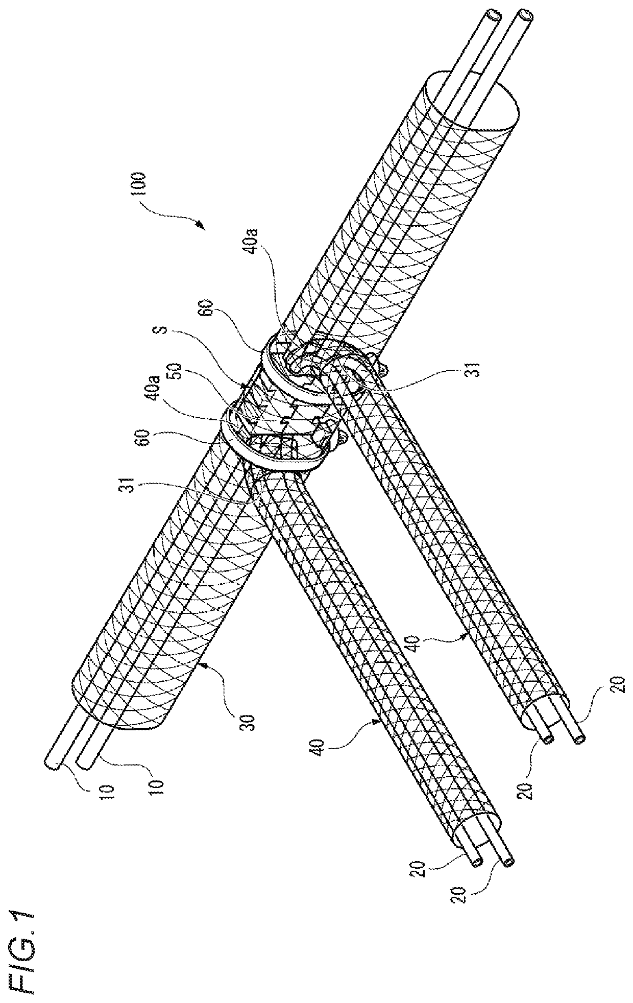
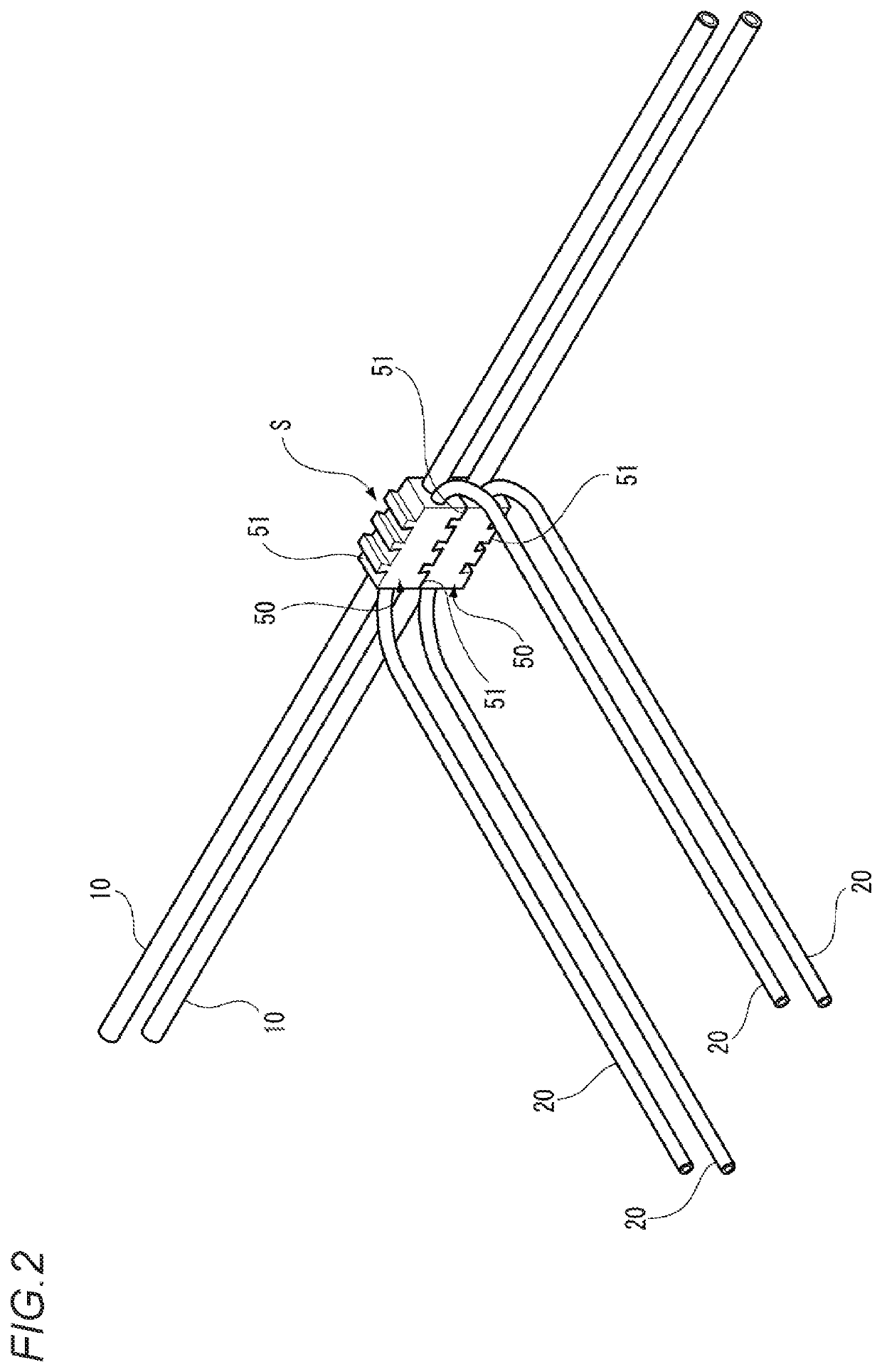
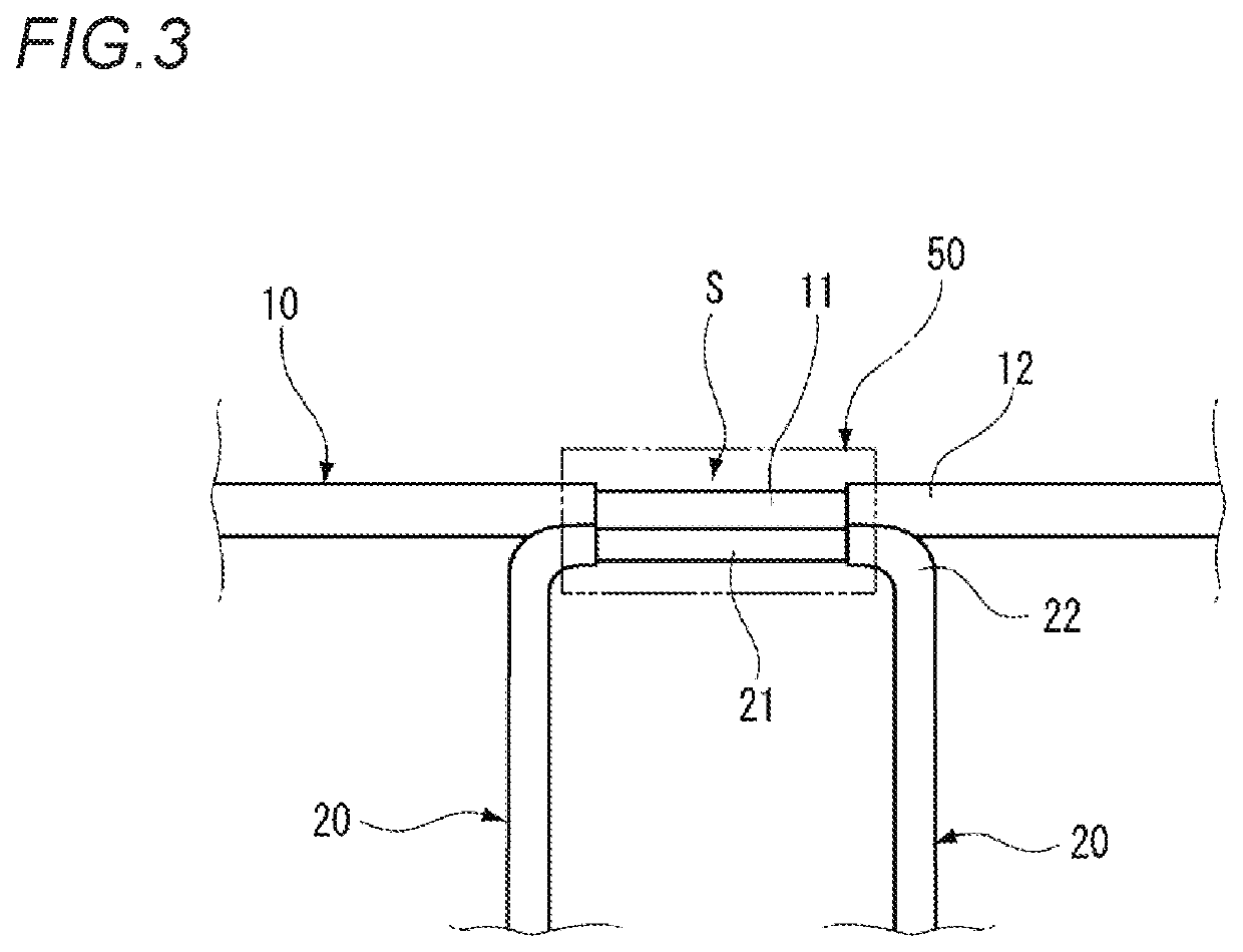
Branching circuit body and branching method of electric wires
a branching method and circuit body technology, applied in the direction of insulated conductors, cable connections, coupling devices, etc., can solve the problems of increasing the number of electric wires, increasing the cost, and increasing the complexity of the structure, so as to simplify the structure and simplify the second electric wire. , the effect of reducing the cos
- Summary
- Abstract
- Description
- Claims
- Application Information
AI Technical Summary
Benefits of technology
Problems solved by technology
Method used
Image

Examples
modification 1
[0082]FIGS. 9A and 9B are perspective views of a branching portion of a branching circuit body 100A according to Modification 1, respectively.
[0083]As illustrated in FIG. 9A, in Modification 1, the end portions 40a of the second shield tubes 40 inserted into the openings 31 of the first shield tube 30 is drawn out through openings 32 on the opposite side to the opening 31. The coupling band 60 is wound around the end portions 40a of the second shield tubes 40 drawn out through openings 32 to be latched by and joined to the first shield tube 30. When coupling the end portions 40a of the second shield tubes 40 with the coupling bands 60, it is preferable that a part of the first shield tube 30 is coupled together.
[0084]According to this Modification 1, the second shield tube 40 is joined to the first shield tube 30 by coupling with the coupling band 60 and thus, the second shield tube 40 can be joined to the first shield tube 30 without a gap, and a good shielding effect can be obtain...
modification 2
[0086]FIGS. 10A and 10B are perspective views of a branching portion S of a branching circuit body 100B according to Modification 2, respectively.
[0087]As illustrated in FIGS. 10A and 10B, in Modification 2, the second shield tubes 40 are joined to the first shield tube 30 by using a holder (holding member) 70 covering the periphery of the branching portion S. The holder 70 is formed from an electrically insulating resin, and has a structure in which a pair of divided holders 71, which are halved vertically, are pivotably connected to each other by a hinge portion (not illustrated). The divided holder 71 includes a main wire recessed portion 75 into which the first shield tube 30 is fitted and a branching wire recessed portion 76 into which the second shield tube 40 is fitted.
[0088]In order to mount the holder 70, first, the first shield tube 30 is fitted into the main wire recessed portion 75 of one divided holder 71 and the second shield tube 40 is fitted into the branching wire r...
modification 3
[0090]FIG. 11 is a perspective view of the branching portion S of a branching circuit body 100C according to Modification 3.
[0091]As illustrated in FIG. 11, in Modification 3, an edge of the opening 31 of the first shield tube 30 and the periphery of the second shield tube 40 inserted into the opening 31 are joined by a welding unit. As a way of joining by the welding unit, there are, for example, pressure weldings such as ultrasonic joining, welding, brazing, and the like. Further, the edge of the opening 31 of the first shield tube 30 and the periphery of the second shield tube 40 can be joined by a mechanical coupling unit using a stapler or the like.
[0092]According to Modification 3, the second shield tube 40 is joined at a welded portion C. Therefore, the second shield tube 40 can be easily joined to the first shield tube 30 without a gap, and a good shielding effect can be obtained.
[0093]Next, an electric wire branching method for branching electric wires to obtain a branching...
PUM
| Property | Measurement | Unit |
|---|---|---|
| size | aaaaa | aaaaa |
| degree of freedom | aaaaa | aaaaa |
| shielding effect | aaaaa | aaaaa |
Abstract
Description
Claims
Application Information