Methods and apparatuses for encoding and decoding digital light field images

a technology of light field images and methods, applied in electrical apparatus, digital video signal modification, pictoral communication, etc., can solve the problems of inability to know the directional distribution of light, inability to compress light field images, and inability to achieve efficient compression, so as to avoid redundancy

Active Publication Date: 2021-01-05
SISVEL TECH
View PDF10 Cites 0 Cited by
  • Summary
  • Abstract
  • Description
  • Claims
  • Application Information

AI Technical Summary

Benefits of technology

[0056]The present invention aims to solve these and other problems by providing a method and an apparatus for encoding and / or decoding digital images provided by light field cameras. The basic idea of the present invention is to generate a new compact light field image data representation that avoids redundancy due to demosaicing and scaling; the new representation is efficiently compressed using graph signal processing (GSP) techniques. Conversely, in the decoding stage inverse GSP techniques are performed.

Problems solved by technology

However, this 2D image contains no information about the directional distribution of the light that strikes the photo-sensor.
Compression of light field images is an important problem for computational photography.
Due to the 4D nature of light fields, and the fact that 2D slices of light fields are equivalent to conventional pictures, the uncompressed files tend to be big, and may take up to gigabytes of space.
These approaches do not utilize the information and redundancy specific to light field images, but rather treat them as general images.
Because of the division of images into blocks, JPEG and other block-based compression techniques are known to have the problem of generating “blocking artifacts”, in which the compressed image appears to be composed of blocks or has other introduced vertical / horizontal artifacts (e.g., vertical or horizontal lines, discontinuities, or streaks).
However, due to the quasi-periodic nature of light field images, and the blocky nature of the compression, the results tend to be poor, including noticeable blocking artifacts.
Such blocking artifacts may severely damage the angular information in the light field image, and therefore may limit the horizontal and vertical parallax that can be achieved using these images.
However, the aforementioned existing works require pre-processing stages which increase data representation redundancy prior to compression.
Although, the down-sampling of U and V components reduces the redundancy introduced by the demosaicing and scaling, however, the rounding effect during the color conversion may introduce other distortion.
Regarding the problem of compressing light field images, some pre-processing stages increase data representation redundancy prior to compression.
However, the existing compression technique all require full colored subaperture images as input.
Although, the downsampling of U and V components reduces the redundancy introduced by the demosaicing and scaling, the rounding effect during the color conversion may introduce other distortion.

Method used


Image

  • Methods and apparatuses for encoding and decoding digital light field images
  • Methods and apparatuses for encoding and decoding digital light field images
  • Methods and apparatuses for encoding and decoding digital light field images

Examples


Embodiment Construction

[0079]In this description, any reference to “an embodiment” will indicate that a particular configuration, structure or feature described in regard to the implementation of the invention is comprised in at least one embodiment. Therefore, the phrase “in an embodiment” and other similar phrases, which may be present in different parts of this description, will not necessarily be all related to the same embodiment. Furthermore, any particular configuration, structure or feature may be combined in one or more embodiments in any way deemed appropriate.

[0080]The references below are therefore used only for sake of simplicity, and do not limit the protection scope or extension of the various embodiments.

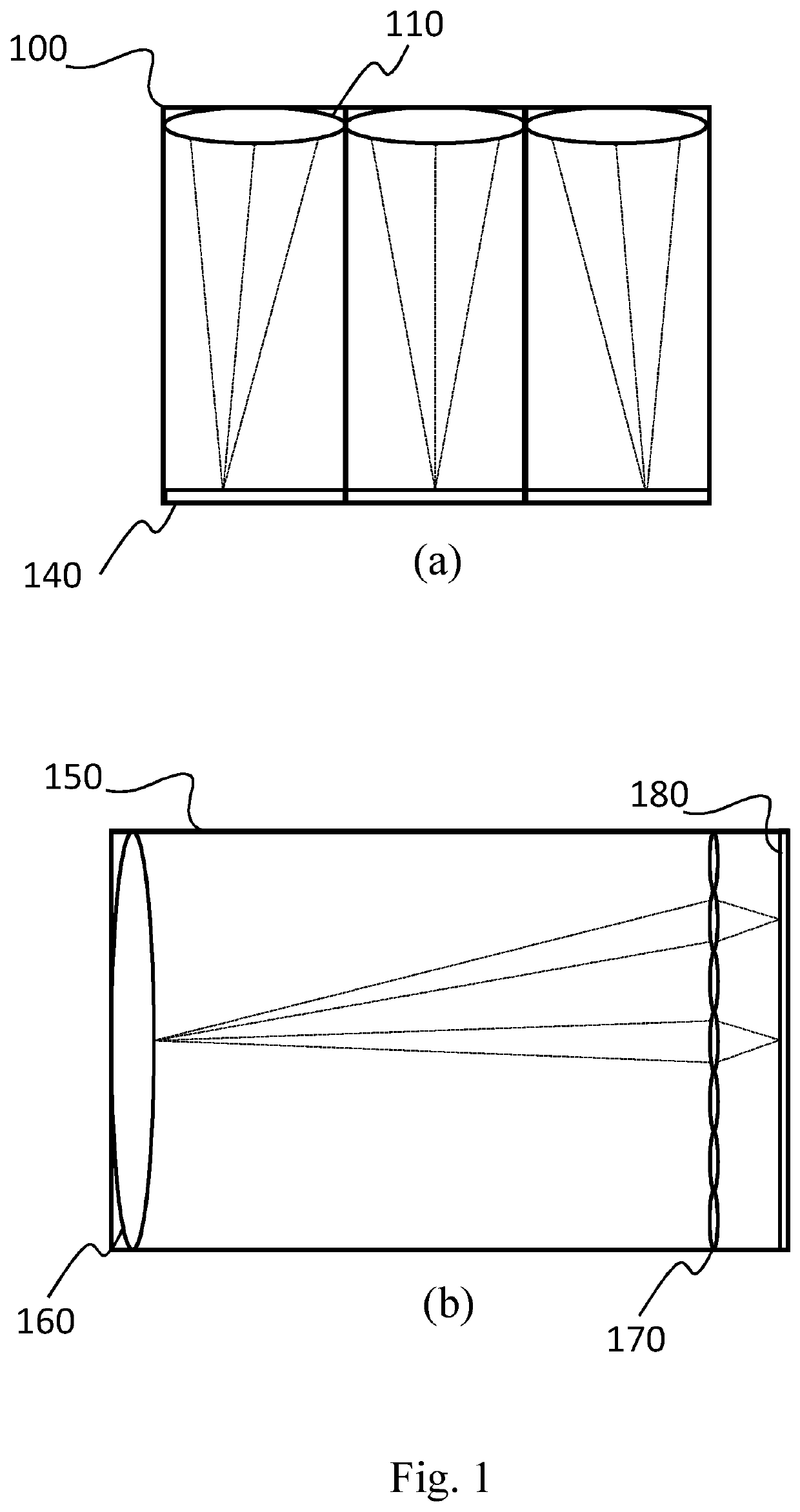
[0081]With reference to FIG. 10, an apparatus 1005 for compressing digital images or video streams (also named encoding apparatus 1005) comprises the following parts:[0082]a processing unit 1010, like a Central Processing Unit (CPU), configured for executing a set of instructions for carry...


PUM


Abstract

A method for encoding a raw lenselet image includes a receiving phase, wherein at least a portion of a raw lenselet image is received, the image including a plurality of macro-pixels, each macro-pixel having pixels corresponding to a specific view angle for the same point of a scene, and an output phase, wherein a bitstream having at least a portion of an encoded lenselet image is outputted. The method has an image transform phase, wherein the pixels of said raw lenselet image are spatially displaced in a transformed multi-color image having a larger number of columns and rows with respect to the received raw lenselet image, wherein dummy pixels having undefined value are inserted into the raw lenselet image and wherein the displacement is performed so as to put the estimated center location of each macro-pixel onto integer pixel locations. Moreover, the method includes a sub-view generation phase, wherein a sequence of sub-views is generated, said sub-views having pixels of the same angular coordinates extracted from different macro-pixels of the transformed raw lenselet image. Finally, the method has a graph coding phase, wherein a bitstream is generated by encoding a graph representation of at least one of the sub-views of the sequence according to a predefined graph signal processing technique.

Description

FIELD OF THE INVENTION[0001]The present invention relates to a method and an apparatus for encoding and / or decoding digital images; in particular, for coding and / or decoding digital images provided by the so-called light field cameras.DESCRIPTION OF THE PRIOR ART[0002]During operation, a conventional digital camera captures a two-dimensional (2D) image representing a total amount of light that strikes each point on a photo-sensor within the camera. However, this 2D image contains no information about the directional distribution of the light that strikes the photo-sensor.[0003]In contrast, light field cameras sample the four-dimensional (4D) optical phase space or light field and in doing so capture information about the directional distribution of the light rays. Directional information at the pixels corresponds to locational information at the aperture.[0004]This information captured by light field cameras may be referred to as the light field, the plenoptic function, or radiance....

Claims


Application Information

Patent Timeline
Patent Type & Authority Patents(United States)
IPC IPC(8): H04N19/46H04N19/176H04N19/117H04N19/182H04N13/229H04N13/232H04N13/161
CPCH04N19/176H04N13/161H04N13/229H04N13/232H04N19/117H04N19/182H04N19/46H04N19/597H04N19/10H04N19/649H04N19/88
Inventor CHAO, YUNG-HSUANCHEUNG, GENEORTEGA, ANTONIO
Owner SISVEL TECH
Why Eureka
Try Eureka