Solar chargeable battery for portable devices

a solar energy and portable device technology, applied in the direction of secondary cell servicing/maintenance, electrochemical generators, transportation and packaging, etc., can solve the problems of inconvenient use, limited mobility of charging systems, and general inability of pv cells to provide a continuously stable energy source, so as to avoid redundancy or conflict

Inactive Publication Date: 2012-07-12
SUNCORE CORPORATION
View PDF9 Cites 35 Cited by
  • Summary
  • Abstract
  • Description
  • Claims
  • Application Information

AI Technical Summary

Benefits of technology

[0008]The power regulator operates with a predetermined regulated voltage level in the first mode and operates with an adjustable regulated voltage level in the second mode. That is, the power regulator charges the battery to the predetermined regulated voltage level in the first mode and charges the battery to the adjustable regulated voltage level in the second mode. In one application, the battery is a lithium based battery and the predetermined regulated voltage is about 4.2V. In the second mode, the adjustable regulated voltage level tracks the voltage level of the variable DC power source and is approximately equal to the voltage level of the variable DC power source less a predetermined amount. The different modes of operation allow the power regulator to efficiently charge or recharge the battery under various light conditions. The adjustable regulated voltage level also allows the power regulator to continue providing accurate (or well-controlled) voltage regulation and current regulation over a range of lighting conditions.
[0014]In one embodiment, the battery charging circuit includes a direction resistor configured for coupling between the battery and a battery terminal of the portable device. The controller monitors the direction resistor for current flow. Current flowing from the portable device to the battery indicates that an external power source (e.g., an AC adapter, a car adapter, or a USB interface) is connected to the portable device and attempting to charge the battery. Current flowing from the battery to the portable device indicates that the portable device is active. In some implementations, the controller disables the power regulator to avoid redundancy or conflict when the external power source (e.g., a substantially fixed DC power source) is available to charge the battery as indicated by the direction resistor. In some applications, the controller also selectively disables the power regulator to reduce EMI when the direction resistor indicates that the portable device (e.g., a cell phone) is active or being used.

Problems solved by technology

The tethered charging systems limit mobility and may inconvenience users.
However, the PV cells generally cannot provide a continuously stable energy source like the tethered charging systems.
That is, the electrical energy from the PV cells fluctuates when lighting conditions change and charging the battery becomes a challenge.

Method used


Image

  • Solar chargeable battery for portable devices
  • Solar chargeable battery for portable devices
  • Solar chargeable battery for portable devices

Examples


Embodiment Construction

[0025]The present invention relates to a method and an apparatus for charging a battery using a variable power source such as solar energy or light. While the specification describes several example embodiments of the invention, it should be understood that the invention can be implemented in many ways and is not limited to the particular examples described below or to the particular manner in which any features of such examples are implemented.

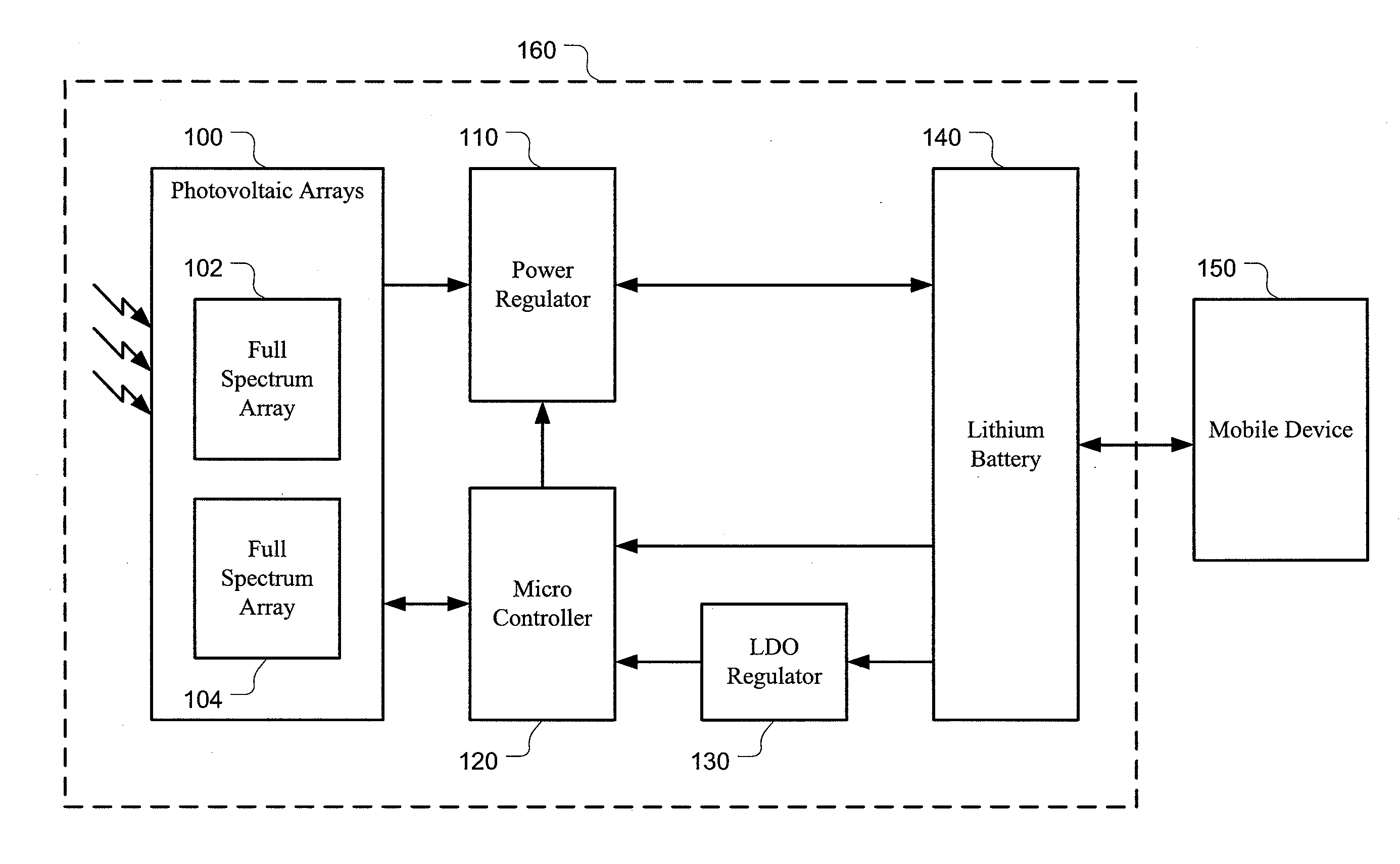
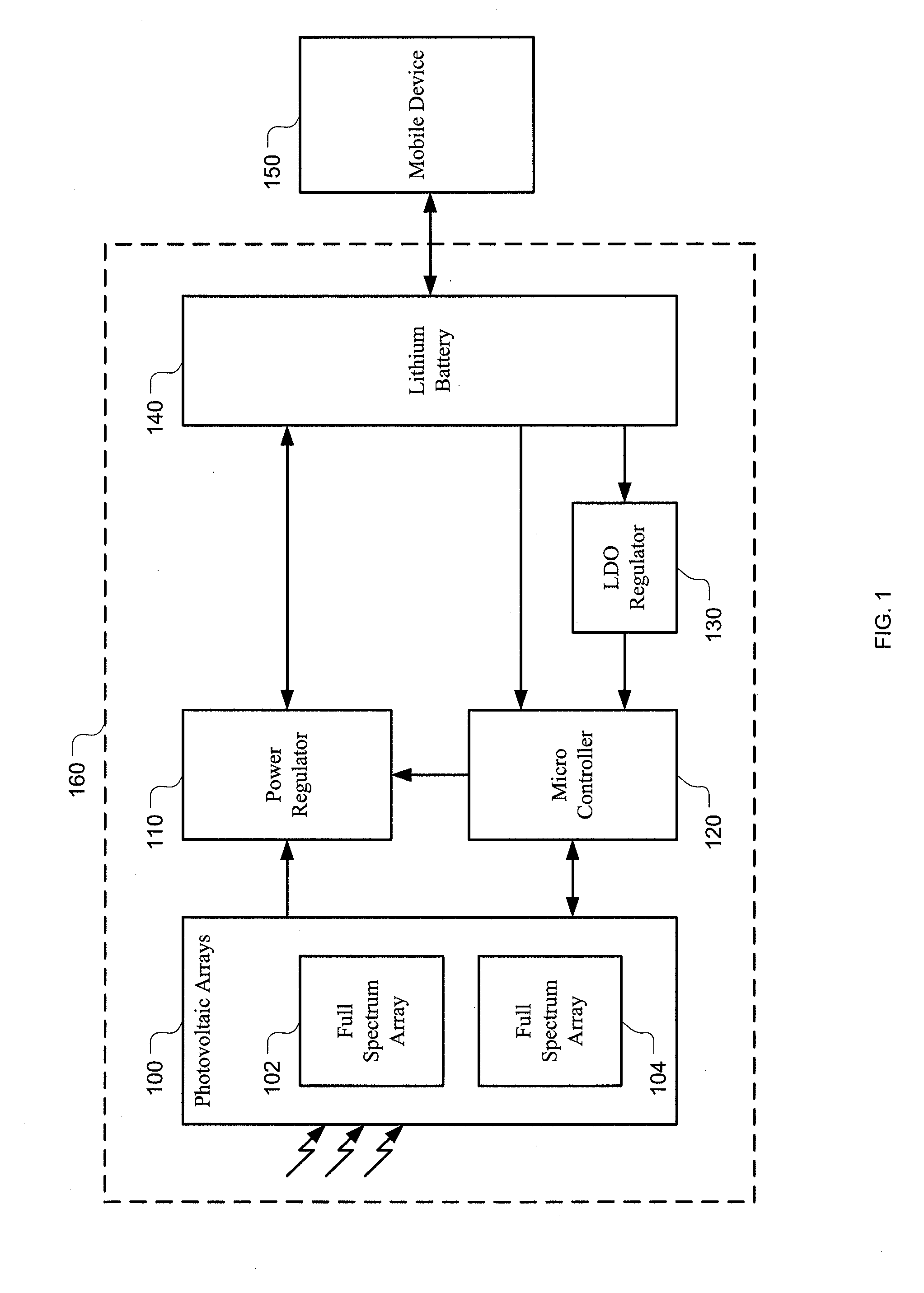
[0026]As described above, PV cells can be used to convert solar energy or light into electrical energy for charging a battery. FIG. 1 is a block diagram of one embodiment of a solar chargeable battery system 160 comprising a PV array 100 with one or more PV cells 102, 104. The PV array 100 outputs a substantially DC power source at a voltage level and a current level that vary with lighting conditions. For example, the voltage and / or current provided by the PV array 100 varies greatly depending upon the density and the wavelength of available...


PUM

PropertyMeasurementUnit
voltageaaaaaaaaaa
voltageaaaaaaaaaa
thickaaaaaaaaaa

Abstract

A solar chargeable battery comprises a built-in photovoltaic array and a programmable battery charging circuit. The photovoltaic array provides a variable power source in response to light. The battery charging circuit receives the variable power source and operates in different modes to charge the battery over a range of lighting conditions. For example, the battery charging circuit charges the battery to a substantially fixed regulated voltage level in a first mode when a voltage level of the variable power source is above a predefined threshold. The battery charging circuit charges the battery to an adjustable regulated voltage level in a second mode when the voltage level of the variable power source is below the predefined threshold.

Description

CROSS-REFERENCE TO RELATED APPLICATIONS[0001]This application is a continuation of U.S. patent application Ser. No. 12 / 389,332, filed Feb. 19, 2009 entitled “SOLAR CHARGEABLE BATTERY FOR PORTABLE DEVICES”, which is hereby incorporated by reference in its entirety.BACKGROUND[0002]1. Field[0003]This disclosure relates generally to battery charging circuits and solar chargeable replacement batteries for portable devices.[0004]2. Description of the Related Art[0005]Portable communication and entertainment devices (e.g., laptop computers, cameras, cell phones, PDAs, GPS units, music player devices, and other hand-held devices) typically have battery packs that are recharged through tethered charging systems (e.g., AC adapters or USB interfaces). The tethered charging systems limit mobility and may inconvenience users. Batteries can also be charged using solar energy. For examples, photovoltaic (PV) cells can absorb energy from electromagnetic waves and convert photon energy into electric...

Claims


Application Information

Patent Timeline
Patent Type & Authority Applications(United States)
IPC IPC(8): H01M10/46H02J7/00
CPCH01M10/0525H01M10/4257Y02E60/122H01M10/465H01M10/486H01M10/44Y02E60/10
Inventor ENGLISH, PETERBRIMMER, STEVEN R.
Owner SUNCORE CORPORATION
Why Eureka
Try Eureka