
Dynamometer system

a dynamometer and system technology, applied in the direction of instruments, mechanical equipment, structural/machine measurement, etc., can solve the problem of limited control bandwidth, suppress the resonance of mechanical systems, and achieve high accuracy the effect of simulation, prolonging the control request, and suppressing mechanical system resonan

Active Publication Date: 2021-01-19
MEIDENSHA ELECTRIC MFG CO LTD
View PDF43 Cites 3 Cited by
  • Summary
  • Abstract
  • Description
  • Claims
  • Application Information

AI Technical Summary

Benefits of technology

The present invention relates to an electric inertia control device for a vehicle. The device uses an inertia compensator and a disturbance observer to accurately control the behavior of the vehicle's inertial system. The inertia compensator generates a torque signal by multiplying a higher-level command torque signal and a shaft torque detection signal. The disturbance observer uses the difference between the angular speed detection signal and the shaft torque detection signal to generate a torque signal. The device can extend the control request up to a high bandwidth while preventing instability caused by resonance phenomena in the mechanical system. The invention also includes a resonance suppression control circuit that uses the inertia compensation torque signal to suppress the resonance phenomena. The device can highly accurately control the inertia of the vehicle and compensate for errors in the inertia sensor. The invention is advantageous in preventing instability and achieving high-bandwidth control.

Problems solved by technology

However, in the electric inertia control device 100 of FIG. 15, a plurality of integrators are present, and thus a significant control delay occurs, with the result that the enhancement of a control bandwidth is limited depending on the degree of facility resonance.

Method used


Image

  • Dynamometer system
  • Dynamometer system
  • Dynamometer system

Examples


example 1

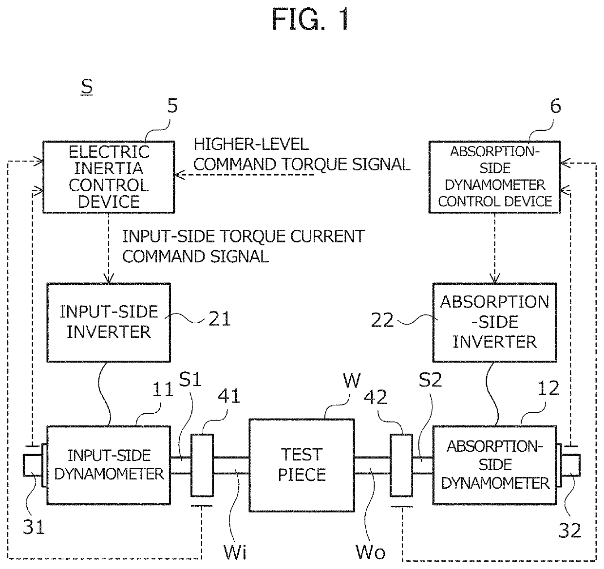
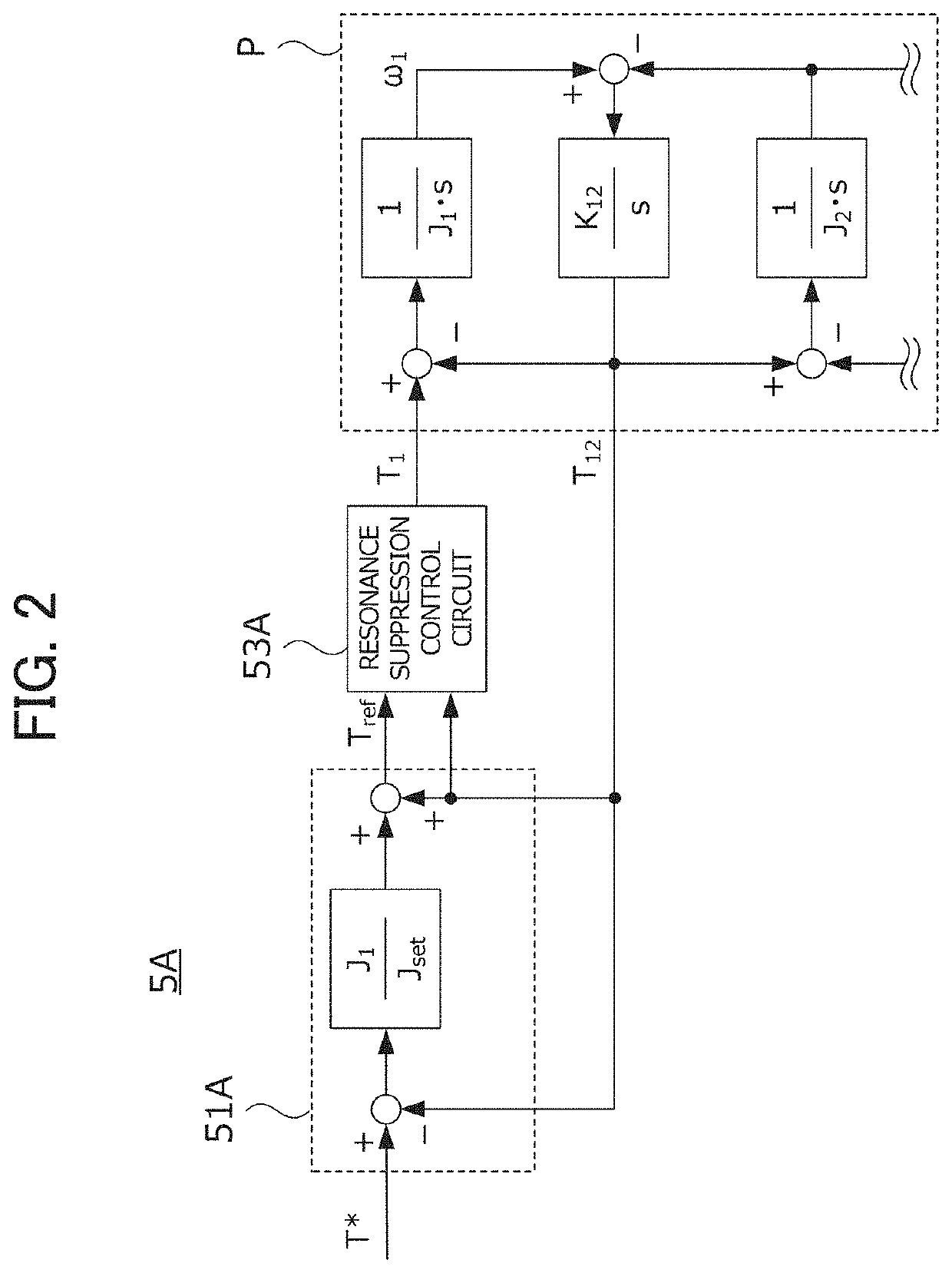
[0046]FIG. 2 is a diagram showing the configuration of a control circuit in the electric inertia control device 5A of example 1. In the electric inertia control device 5A, as described with reference to FIG. 1, a dynamometer system formed by coupling the input shaft of a test piece and an input-side dynamometer through an input-side coupling shaft and coupling the output shaft of the test piece and an absorption-side dynamometer through an absorption-side coupling shaft is a control target P.

[0047]In the following description, a Laplace operator is represented by “s”, a moment of inertia [kgm2] of the input-side dynamometer is represented by “J1”, a moment of inertia [kgm2] of the test piece is represented by “J2” and the shaft rigidity [Nm / rad] of the input-side coupling shaft is represented by “K12”. Among these parameters, at least a specific value of the moment of inertia J1 is assumed to be known.

[0048]Moreover, in the following description, a higher-level command torque signal...

example 2

[0058]The electric inertia control device 5B of example 2 will then be described with reference to FIG. 6. In the following description, the same configurations as those of the electric inertia control device 5A in example 1 are identified with the same reference numerals, and the detailed description thereof will be omitted.

[0059]FIG. 6 is a diagram showing the configuration of a control circuit in the electric inertia control device 5B of example 2. The electric inertia control device 5B includes: an inertia compensator 51B which generates, based on the higher-level command torque signal T* and the input-side shaft torque detection signal T12, the inertia compensation torque signal Tref that simulates the inertial body having the predetermined set moment of inertia Jset; the resonance suppression control circuit 53A; and a disturbance observer 57B which uses a difference between an estimation signal obtained by using the inertia compensator 51B and a detection signal obtained by u...

example 3

[0066]The electric inertia control device 5C of example 3 will then be described with reference to FIG. 9. In the following description, the same configurations as those of the electric inertia control device 5A in example 1 are identified with the same reference numerals, and the detailed description thereof will be omitted.

[0067]FIG. 9 is a diagram showing the configuration of a control circuit in the electric inertia control device 5C of example 3. The electric inertia control device 5C includes: an inertia compensator 51C which generates, based on the higher-level command torque signal T* and the input-side shaft torque detection signal T12, the inertia compensation torque signal Tref that simulates the inertial body having the predetermined set moment of inertia Jset; the resonance suppression control circuit 53A; and a disturbance observer 57C which uses a difference between an estimation signal obtained by using the inertia compensator 51C and a detection signal obtained by u...


PUM

PropertyMeasurementUnit
torqueaaaaaaaaaa
angular speed detectionaaaaaaaaaa
speedaaaaaaaaaa

Abstract

An electric inertia control device 5A simulates the behavior of an inertial body having a predetermined set moment of inertia Jset by means of a dynamometer, and is provided with: an inertia compensator 51A which generates a torque signal by multiplying a signal obtained by subtracting a shaft torque detection signal T12 from a higher-level command torque signal T* by the ratio of a moment of inertia J1 of the dynamometer to the set moment of inertia Jset, and generates an inertia compensation torque signal Tref by summing the torque signal and the shaft torque detection signal J1; and a resonance suppression control circuit 53A which uses the inertia compensation torque signal Tref and the shaft torque detection signal T12 to generate a torque current command signal T1 in such a way as to suppress resonance in a mechanical system including a test piece and the dynamometer.

Description

TECHNICAL FIELD[0001]The present invention relates to electric inertia control devices. More specifically, the present invention relates to an electric inertia control device which simulates, in a dynamometer system where a dynamometer is connected to the input shaft or the output shaft of a test piece, the behavior of an inertial body having predetermined set inertia by the dynamometer.BACKGROUND ART[0002]A drive train collectively refers to a plurality of devices for transmitting energy generated in an engine to a drive wheel, and is formed with the engine, a clutch, a transmission, a drive shaft, a propeller shaft, a differential gear, the drive wheel and the like. In a performance evaluation test of the drive train, the transmission actually continues to be driven in the engine, and thus the durability, the quality and the like thereof are evaluated. In recent years, it has been proposed that a dynamometer system in which a dynamometer is coupled to the output shaft or the input...

Claims


Application Information

Patent Timeline
Patent Type & Authority Patents(United States)
IPC IPC(8): G01M17/007G01L3/16G01L3/04F16H61/00
CPCG01L3/16G01L3/04G01M17/007F16H2061/0078G01M13/025
Inventor YAMAGUCHI, TAKASHIAKIYAMA, TAKAO
Owner MEIDENSHA ELECTRIC MFG CO LTD
Learn More