

Electric inertia control device
a control device and inertia technology, applied in the direction of instruments, mechanical devices, structural/machine measurement, etc., can solve the problems of limited control bandwidth, suppress the resonance of mechanical systems, and achieve high accuracy the effect of simulation, extension of control requests, and suppression of mechanical system resonan
- Summary
- Abstract
- Description
- Claims
- Application Information
AI Technical Summary
Benefits of technology
Problems solved by technology
Method used
Image

Examples
example 1
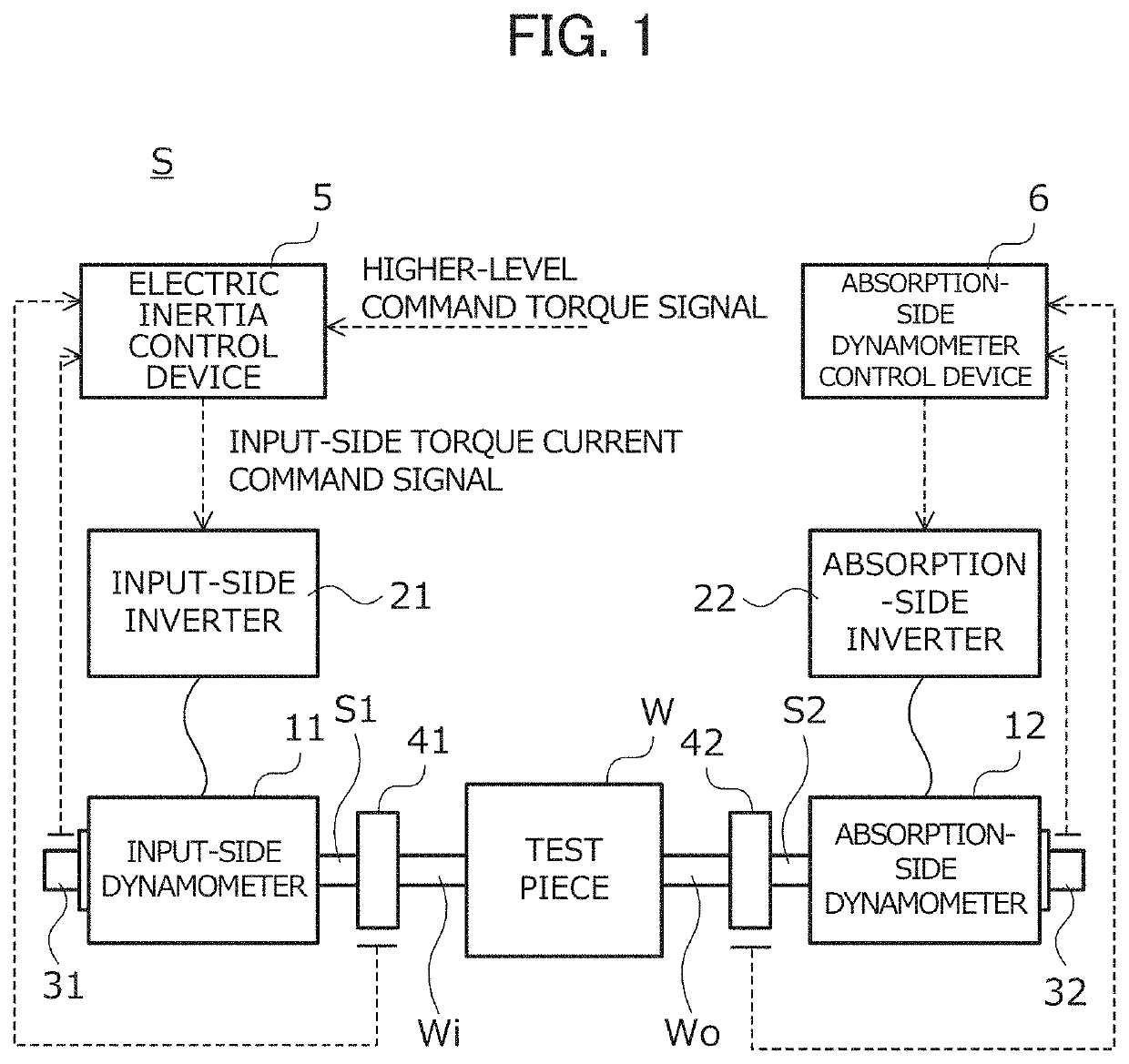
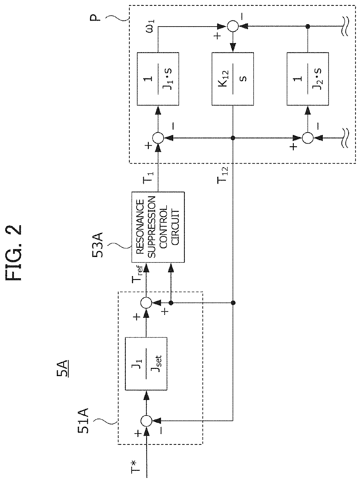
[0045]FIG. 2 is a diagram showing the configuration of a control circuit in the electric inertia control device 5A of example 1. In the electric inertia control device 5A, as described with reference to FIG. 1, a dynamometer system formed by coupling the input shaft of a test piece and an input-side dynamometer through an input-side coupling shaft and coupling the output shaft of the test piece and an absorption-side dynamometer through an absorption-side coupling shaft is a control target P.
[0046]In the following description, a Laplace operator is represented by “s”, a moment of inertia [kgm2] of the input-side dynamometer is represented by “J1”, a moment of inertia [kgm2] of the test piece is represented by “J2” and the shaft rigidity [Nm / rad] of the input-side coupling shaft is represented by “K12”. Among these parameters, at least a specific value of the moment of inertia J1 is assumed to be known.
[0047]Moreover, in the following description, a higher-level command torque signal...
example 2
[0057]The electric inertia control device 5B of example 2 will then be described with reference to FIG. 6. In the following description, the same configurations as those of the electric inertia control device 5A in example 1 are identified with the same reference numerals, and the detailed description thereof will be omitted.
[0058]FIG. 6 is a diagram showing the configuration of a control circuit in the electric inertia control device 5B of example 2. The electric inertia control device 5B includes: an inertia compensator 51B which generates, based on the higher-level command torque signal T* and the input-side shaft torque detection signal T12, the inertia compensation torque signal Tref that simulates the inertial body having the predetermined set moment of inertia Jset; the resonance suppression control circuit 53A; and a disturbance observer 57B which uses a difference between an estimation signal obtained by using the inertia compensator 51B and a detection signal obtained by u...
example 3
[0065]The electric inertia control device 5C of example 3 will then be described with reference to FIG. 9. In the following description, the same configurations as those of the electric inertia control device 5A in example 1 are identified with the same reference numerals, and the detailed description thereof will be omitted.
[0066]FIG. 9 is a diagram showing the configuration of a control circuit in the electric inertia control device 5C of example 3. The electric inertia control device 5C includes: an inertia compensator 51C which generates, based on the higher-level command torque signal T* and the input-side shaft torque detection signal T12, the inertia compensation torque signal Tref that simulates the inertial body having the predetermined set moment of inertia Jset; the resonance suppression control circuit 53A; and a disturbance observer 57C which uses a difference between an estimation signal obtained by using the inertia compensator 51C and a detection signal obtained by u...
PUM
| Property | Measurement | Unit |
|---|---|---|
| torque | aaaaa | aaaaa |
| angular speed detection | aaaaa | aaaaa |
| angular speed | aaaaa | aaaaa |
Abstract
Description
Claims
Application Information