Powder press and a feed housing having preferably a plurality of stamps which are movable for a transverse press

a technology of transverse press and feed housing, which is applied in the direction of presses, shaping presses, manufacturing tools, etc., can solve the problems of insufficient stability of stop and inadvertent change of stamp position, and achieve the effect of accurate pressing position and simple handling

Active Publication Date: 2021-01-26
KRAMER DIETMAR W
View PDF35 Cites 0 Cited by
  • Summary
  • Abstract
  • Description
  • Claims
  • Application Information

AI Technical Summary

Benefits of technology

[0003]In contrast, it is the object of the present invention to improve a press device, in particular for the transverse pressing of a powder press, such that it guarantees very stable positioning of the transverse press stamp, even with very high pressing forces, and the pressing position of this transverse press stamp can additionally be adjusted easily and very accurately.
[0006]With this type of wedge arrangement one can on the one hand achieve very accurate pressing positions of these stamps, and on the other hand this arrangement enables exceptionally stable positioning of the stamps that are to be pressed with high pressures.
[0007]Advantageously, the wedge arrangements are formed with wedge surfaces which have an angle of a few angular degrees in relation to their longitudinal extension so that this wedge arrangement is in the self-inhibiting range. This enables the stops to permanently remain securely in position as desired for these stamp positionings which are to be implemented numerous times.
[0009]The feed housing with the stamps and the wedge arrangements can thus be produced as one unit, by means of which the desired accurate pressing positions can be achieved optimally by simple handling.

Problems solved by technology

It is a disadvantage here that this type of stop is not sufficiently stable with high pressing forces, and this position of the stamp may change inadvertently.

Method used


Image

  • Powder press and a feed housing having preferably a plurality of stamps which are movable for a transverse press
  • Powder press and a feed housing having preferably a plurality of stamps which are movable for a transverse press
  • Powder press and a feed housing having preferably a plurality of stamps which are movable for a transverse press

Examples


Embodiment Construction

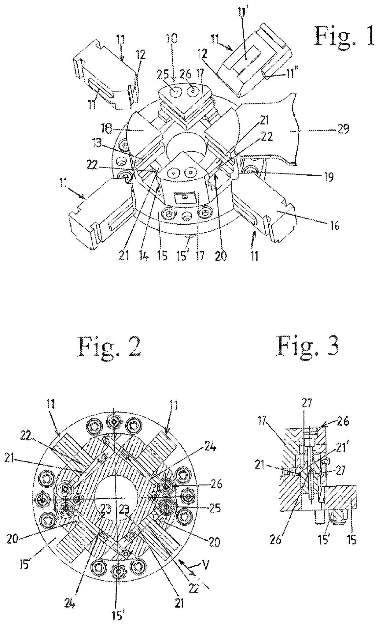
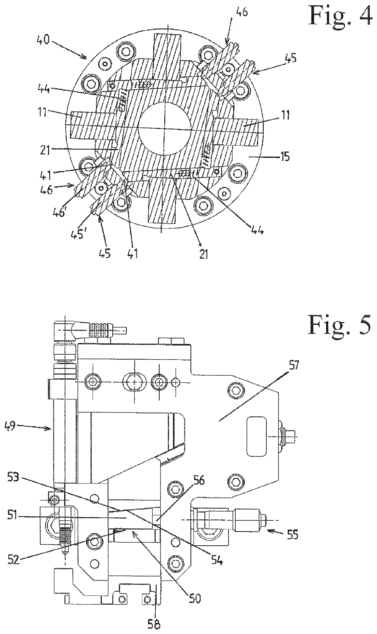
[0019]A feed housing 10 of a powder press according to FIG. 1 and FIG. 2 consists of a base plate 15, guide blocks 17, 18 and of four stamps 11 provided for a transverse press and which can be inserted radially into sliding tracks 13, 14 of the guide blocks 17, 18 with their lateral guide elements 11′, and in the center form part of a matrix with the hollow chamber for the production of a pressed article. For this purpose, corresponding recesses 12 are formed on the front side of the stamps 11 as a negative mould for the pressed article. On the rear side, the stamps 11 are each provided with a T-shaped coupling part 16 which can be coupled to a connector piece of a press device 49 according to FIG. 5.

[0020]In addition, a stamp that can be engaged from above and a stamp that can be engaged from below are provided on the press, but these are not detailed. On its lower side, the base plate 15 has centering pins 15′ and can be appropriately centered on a press structure and be fixed by ...


PUM

PropertyMeasurementUnit
angleaaaaaaaaaa
thicknessaaaaaaaaaa
angleaaaaaaaaaa

Abstract

Powder press having preferably stamps which are movable for a transverse press in a feed housing. The stamps partially delimit a hollow chamber of a matrix in the feed housing and are able to be coupled to a press device by one connector piece each. An adjustable positioning device, which is formed from a wedge arrangement having a stop surface and placed crosswise to the moving direction of the stamp, is allocated to the respective stamp for determining the pressing position thereof. The wedge arrangement includes at least one wedge which is adjustable crosswise to the moving direction of the stamp and has the stop surface which contacts a stop surface at the stamp. Such a wedge arrangement can achieve very accurate pressing positions of the stamp, and extremely stable positioning of the stamp to be pressed with high pressure.

Description

FIELD OF THE INVENTION[0001]The invention relates to a powder press having a plurality of stamps movable for a transverse press in a feed housing, which stamps partially delimit a hollow chamber of a matrix in the feed housing, with an adjustable positioning means being allocated or assigned to the respective stamp for determining its pressing position, and being able to be coupled to a press device by a connector piece, and to a feed housing for a powder press wherein a plurality of stamps are provided for the transverse press, which stamps are collectively mounted such that they can be moved radially within the feed housing and in the center form part of a matrix with the hollow chamber for producing a pressed article.BACKGROUND OF THE INVENTION[0002]A powder press for the production of a pressed article according to publication EP-A-2 103 423 is provided with an upper and a lower stamp arrangement as well as a matrix arrangement which forms a mould cavity into which the powdered ...

Claims


Application Information

Patent Timeline
Patent Type & Authority Patents(United States)
IPC IPC(8): B30B11/00B30B15/06B22F3/03B30B15/00
CPCB30B11/007B22F3/03B30B11/004B30B15/007B30B15/065B30B15/0035
Inventor KRAMER, DIETMAR W
Owner KRAMER DIETMAR W
Why Eureka
Try Eureka