
Frame assembly for windows and sliding doors

a frame and sliding door technology, applied in the field of frame assembly, can solve the problems of obstructing viewing through the panel, reducing visibility, and reducing the size of the frame, and achieve the effect of enhancing or maintaining the stability of the frame and enhancing the viewing through the panel

Active Publication Date: 2021-01-26
SALVONI BRUNO
View PDF44 Cites 3 Cited by
  • Summary
  • Abstract
  • Description
  • Claims
  • Application Information

AI Technical Summary

Benefits of technology

The present invention is a frame assembly for use in various window and door applications. It is designed to enhance the viewing through a panel while maintaining the stability of the frame. The frame is made with a predetermined thickness and width, where the predetermined thickness is significantly reduced relative to the predetermined width. This reduces obstructions to viewing through the panel while keeping the frame stable. The frame assembly can be used in sliding glass door applications and includes a header assembly and a sill assembly interconnected to a securing surface. The frame can be moved relative to the header and sill assemblies. Overall, the invention improves the view through the panel while maintaining the stability of the frame.

Problems solved by technology

Nevertheless, some of the problems with existing impact resistant assemblies are that they often will have a thicker size frame in order to achieve impact resistance.
Consequently, portions of the thicker size frame may overlap with a window or door panel to an extent, at least partially obstructing viewing through the panel and reducing visibility.
Other problems of some existing frame assemblies are that they often have a thinner size frame that may compromise structural stability or impact resistance.

Method used


Image

  • Frame assembly for windows and sliding doors
  • Frame assembly for windows and sliding doors
  • Frame assembly for windows and sliding doors

Examples


Embodiment Construction

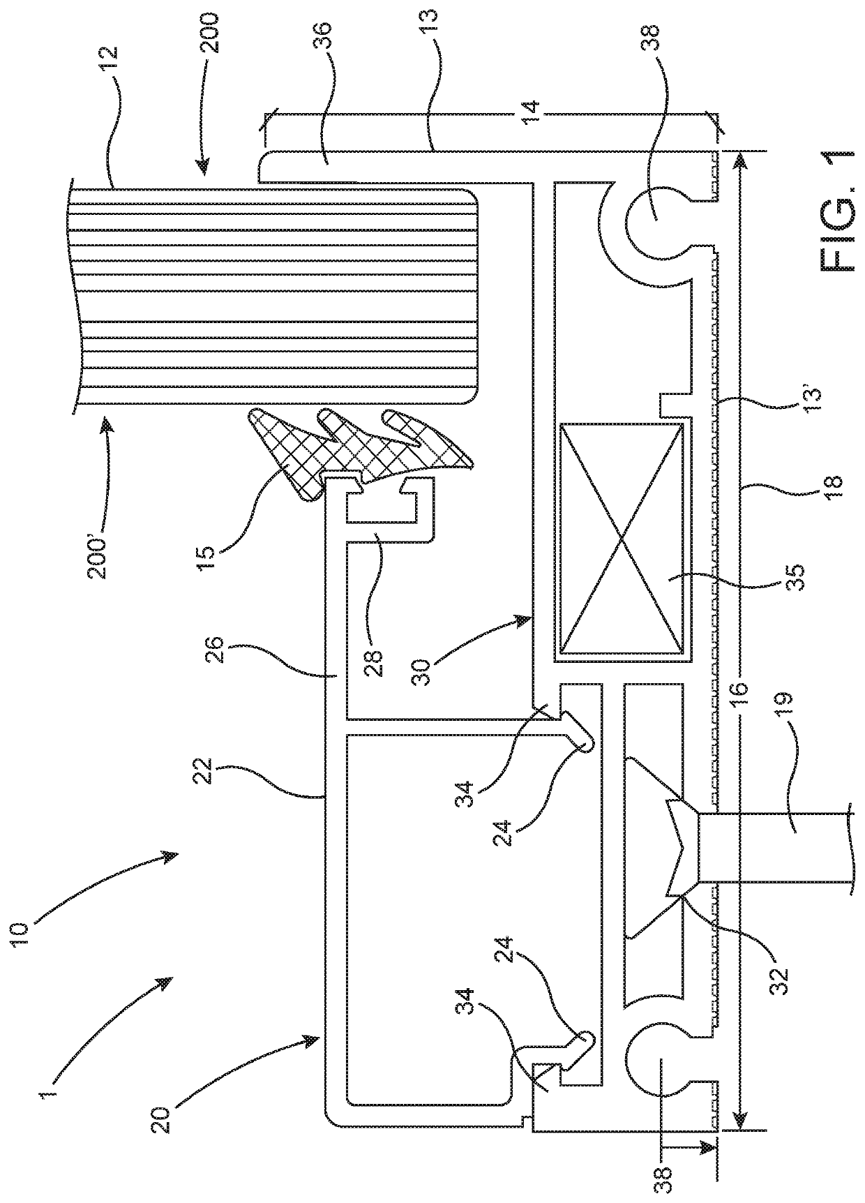
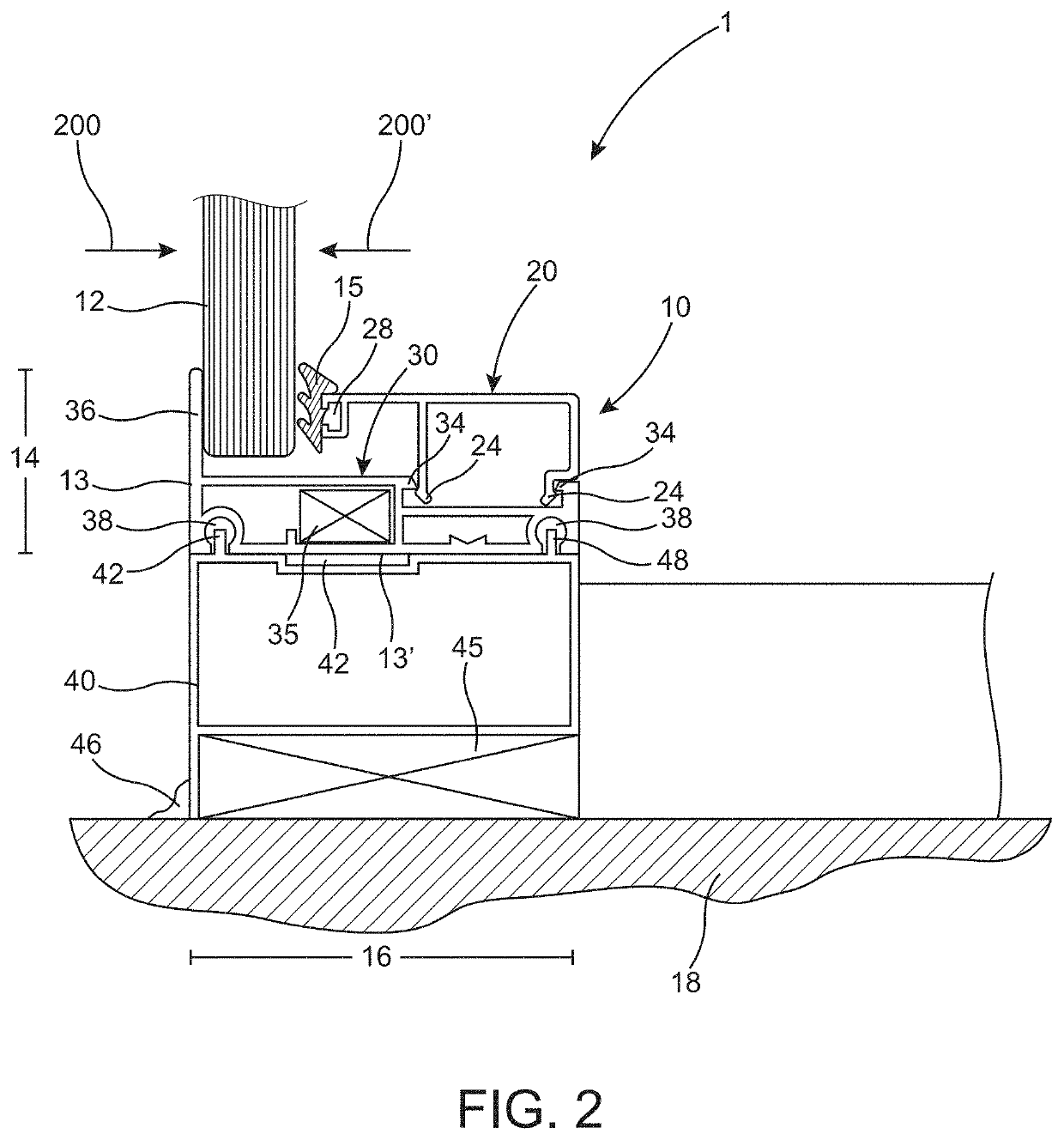
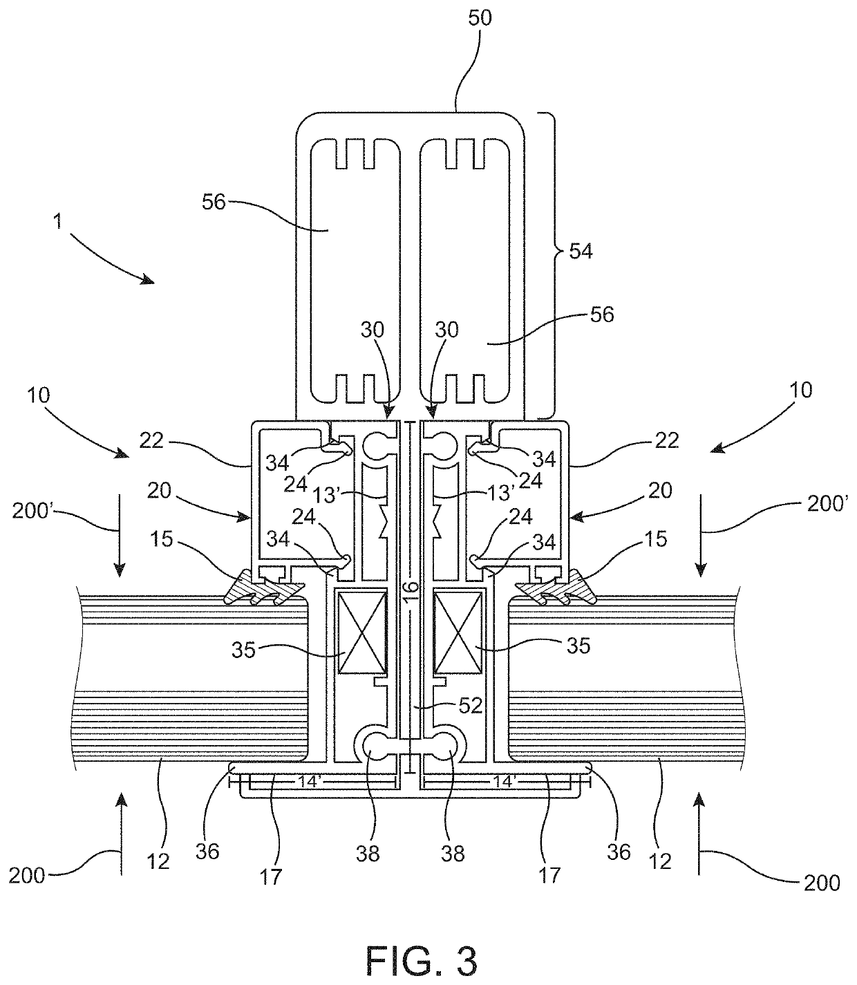
[0049]The present invention is directed to a frame assembly 1 for use in a variety of applications including doors and windows for buildings. The frame assembly 1 of the present invention may also be used in connection with other applications and is not limited to buildings. Generally, the frame assembly 1 comprises a frame 10 structured to retain a panel 12. The panel 12 may be made of a material such as, but not limited to, glass. The frame assembly 1 according to the present invention comprise a frame 10 that can retain a panel 12. The panel 12 may have impact resistant properties.

[0050]As represented in FIG. 1, at least a portion of the frame 10 has a predetermined thickness 14 and a predetermined width 16. The predetermined thickness 14 is substantially less than the predetermined width 16. As a result, the frame 10 has a predetermined thickness 14 with a reduced dimension that is substantially less relative to a purposefully increased dimension of the predetermined width 16. V...


PUM

PropertyMeasurementUnit
widthaaaaaaaaaa
forceaaaaaaaaaa
volumeaaaaaaaaaa

Abstract

A frame assembly, for use in window and door applications configured to retain a panel, comprising a frame with a cover assembly and a support assembly having a track assembly, and a sill assembly and a header assembly both interconnected to a securing surface. The cover assembly is interconnected to the support assembly. The sill assembly comprises a roller member disposed in supporting relation to the track assembly, and the header assembly is disposed in supporting relation to the support assembly so that the frame is movable relative to both the header assembly and the sill assembly. At least a portion of the frame comprises a predetermined thickness of about 1 and 3 / 16 inches and a predetermined width of about 2 and ½ inches. The predetermined thickness is substantially less than the predetermined width so that both cooperatively and concurrently enhance viewing through the panel and the frame's stability.

Description

CLAIM OF PRIORITY[0001]The present application is a Continuation-in-Part to a currently pending Non-Provisional patent application having Ser. No. 15 / 648,666 and a filing date of Jul. 13, 2017 the contents of which are incorporated herein by reference in its entirety.BACKGROUND OF THE INVENTIONField of the Invention[0002]The present invention is directed to a frame assembly comprising a frame configured to retain a panel for use in windows and doors. The frame of the present invention comprises a predetermined thickness having a reduced dimension relative to an increased dimension of a predetermined width of the frame. The predetermined thickness and width of the frame cooperatively enhance viewing through the panel and stability of the frame. The frame assembly of the present invention may also be configured for use in sliding glass doors having multiple tracks.Description of the Related Art[0003]One important aesthetic feature of a window or a sliding glass door is the ability to ...

Claims


Application Information

Patent Timeline
Patent Type & Authority Patents(United States)
IPC IPC(8): E06B3/26E06B3/46E06B1/70
CPCE06B3/4609E06B1/702E06B3/26E06B3/4636E06B3/5821E06B1/6015E06B1/02E06B1/366E06B2003/227E06B1/6092E06B3/9642E06B3/9645E06B3/12E06B3/5454E06B3/305E06B3/922E06B3/469E06B5/11E05B1/0015
Inventor SALVONI, BRUNO
Owner SALVONI BRUNO
Learn More