Reload shaft assembly for surgical stapler

a technology of surgical staplers and shafts, which is applied in the field of surgical staplers, can solve the problems of increased manufacturing burden of surgical staplers, confusion for users, and potential sources of device failur

Active Publication Date: 2021-02-02
APPL MEDICAL RESOURCES CORP
View PDF892 Cites 421 Cited by
  • Summary
  • Abstract
  • Description
  • Claims
  • Application Information

AI Technical Summary

Benefits of technology

[0011]In various embodiments, a reload assembly for a surgical stapling system is provided. The reload assembly comprises an elongate shaft, a jaw assembly, an actuation beam, an articulation link, a support link, and an articulation latching mechanism. The elongate shaft has a proximal end and a distal end and defines a longitudinal axis extending between the proximal end and the distal end. The jaw assembly is articulably coupled to the elongate shaft at the distal end of the elongate shaft. The jaw assembly comprises a first jaw and a second jaw. The first jaw comprises a reload support configured to receive a staple reload. The second jaw is pivotably coupled to the first jaw. The second jaw comprises an anvil surface. The actuation beam is longitudinally slidable within the elongate shaft to actuate the jaw assembly. The actuation beam has a proximal end and a distal end. The articulation link is longitudinally slidable within the elongate shaft to articulate the jaw assembly relative to the elongate shaft. The articulation link has a proximal end positioned adjacent the proximal end of the elongate shaft and a distal end pivotably coupled to the jaw assembly. The support link is longitudinally slidable within the elongate shaft. The support link has a proximal end extending longitudinally to a distal end pivotably coupled to the jaw assembly. The articulation latching mechanism is positioned within the elongate shaft between the proximal end and the distal end. The articulation latching mechanism has an unlatched configuration in which the articulation link and the support link are slidable within the elongate shaft and a latched configuration wherein the articulation latching mechanism engages the articulation link and the support link to prevent longitudinal sliding of the articulation link and the support link.

Problems solved by technology

With these complex mechanisms, surgical staplers can have increased manufacturing burdens, as well as potential sources for device failure and confusion for the user.

Method used


Image

  • Reload shaft assembly for surgical stapler
  • Reload shaft assembly for surgical stapler
  • Reload shaft assembly for surgical stapler

Examples


Embodiment Construction

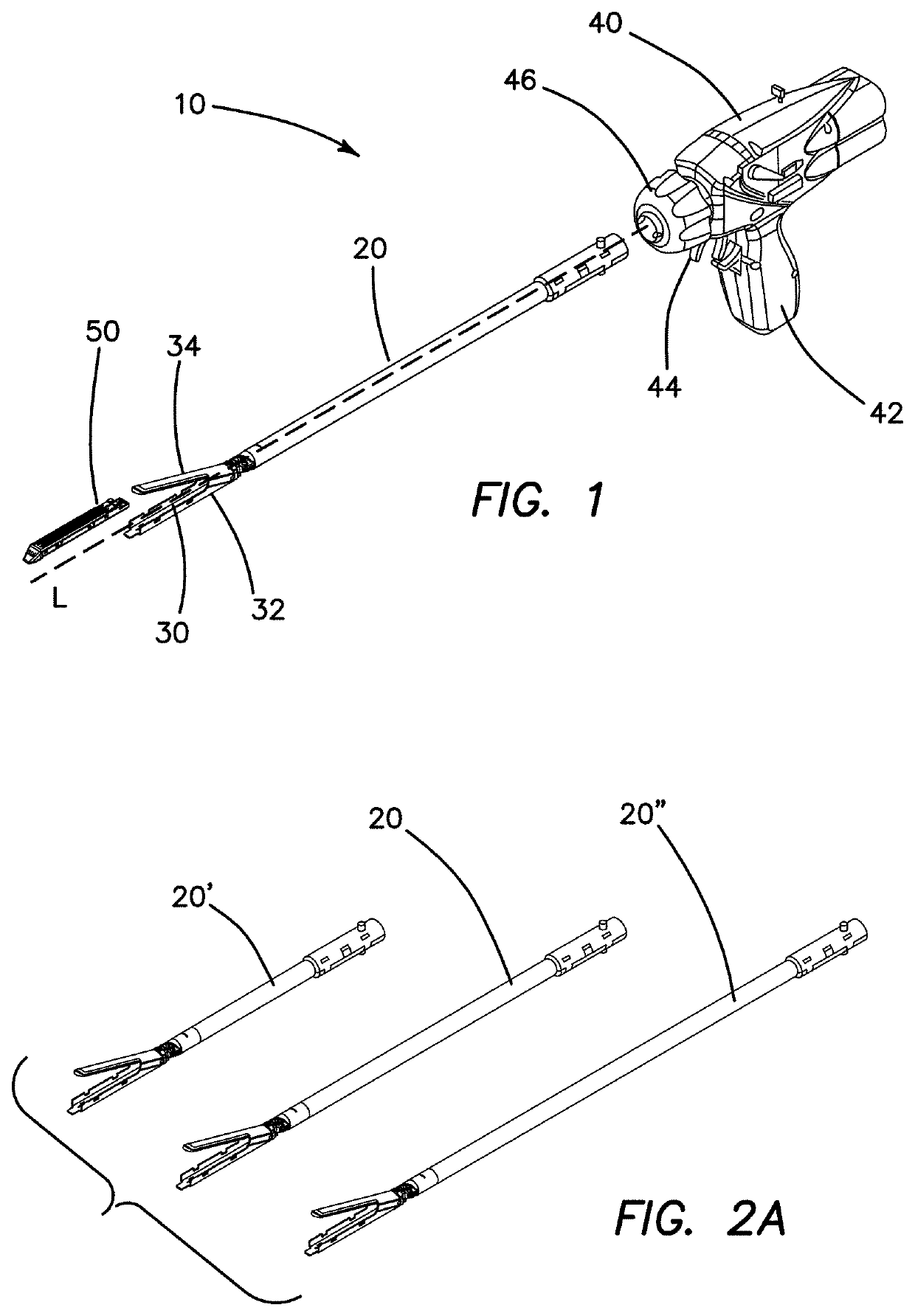
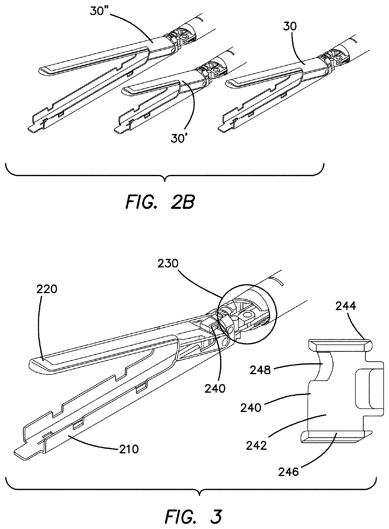
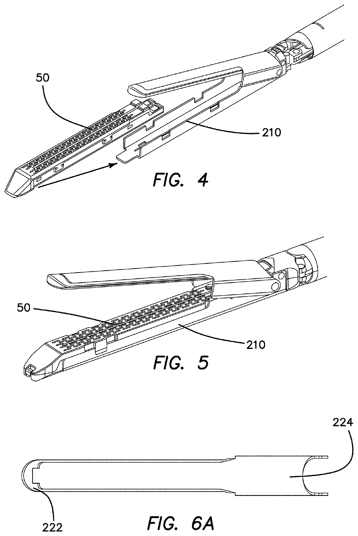
[0069]With reference to FIG. 1, an embodiment of surgical stapling system is illustrated. The illustrated embodiment of surgical stapler 10 comprises an elongate shaft 20, a jaw assembly 30, and a handle assembly 40. FIG. 1 illustrates the surgical stapler 10 with the jaw assembly 30 in an open configuration. A staple reload 50 can be positioned in the jaw assembly. While the illustrated surgical stapling system is illustrated with a powered handle, it is contemplated that the elongate shaft 20 and jaw assembly 30 can be interchangeably used in a stapling system including a mechanical stapler handle. For example, it is contemplated that the various embodiments of elongate shaft assembly 20 and jaw assembly 20 described herein can be used interchangeably with either the powered handle assemblies described in U.S. patent application Ser. No. 15 / 486,008, entitled “SURGICAL STAPLER HAVING A POWERED HANDLE,” filed Apr. 12, 2017, currently pending, and the mechanical manually actuated han...


PUM


Abstract

A surgical stapling system can include a reload shaft. The shaft can include an elongate tubular member with have a jaw assembly at the distal end thereof and a coupling collar at the proximal end thereof. The shaft assembly also includes an articulation joint coupling the jaw assembly to the distal end. A drive member and an articulation member extend within the tubular body of the shaft from the proximal end to the distal end. A firing member is connected to the distal end of the drive member such that advancement of the drive beam advances the firing member to close the jaw assemblies and fire staples from a reload positioned in the jaw assembly. The shaft assembly can also include a lockout mechanism to prevent a firing operation on a previously-fired reload or no reload.

Description

CROSS REFERENCE TO RELATED APPLICATION[0001]This application claims the benefit of U.S. Provisional Patent Application Ser. No. 62 / 321,618, entitled “RELOAD SHAFT ASSEMBLY FOR SURGICAL STAPLER,” filed Apr. 12, 2016. The above-referenced application is incorporated by reference herein in its entirety.BACKGROUND OF THE INVENTIONField of the Invention[0002]The present application relates generally to surgical occlusion instruments and, more particularly, to surgical staplers.Description of the Related Art[0003]Surgical staplers are used to approximate or clamp tissue and to staple the clamped tissue together. As such, surgical staplers have mechanisms to ensure that tissue is properly positioned and captured and to drive staples through the tissue. As a result, this has produced, for example, multiple triggers and handles in conjunction with complex mechanisms to provide proper stapling of the clamped tissue. With these complex mechanisms, surgical staplers can have increased manufactu...

Claims


Application Information

Patent Timeline
Patent Type & Authority Patents(United States)
IPC IPC(8): A61B17/072A61B90/00A61B17/29A61B17/00A61B90/90
CPCA61B17/07207A61B17/072A61B90/90A61B2017/0046A61B2017/00477A61B2017/00526A61B2017/07257A61B2017/07264A61B2017/07278A61B2017/07285A61B2017/2927A61B2090/038A61B2090/0808A61B2090/0814A61B17/0682A61B17/115A61B2017/2903A61B2017/2941A61B2017/2943A61B2017/2946
Inventor JASEMIAN, BABAK D.DECKER, STEVEN E.PATEL, ATAL C.NELSON, ERIKMCCARTHY, ANDREW J.ZIMMERMAN, SCOTTHOPKINS, TIMOTHY M.SCHOBER, JOSHUA M.WEISS, ERIC J.BECERRA, MATTHEW M.REED, CHRISTINA N.
Owner APPL MEDICAL RESOURCES CORP
Why Eureka
Try Eureka