
Foldable brake pedal apparatus for autonomous vehicle

a brake pedal and autonomous vehicle technology, applied in the direction of pedestrian/occupant safety arrangement, mechanical control devices, instruments, etc., can solve the problems of affecting the driver's rest, accidents may occur according, etc., and achieve the effect of improving stability

Active Publication Date: 2021-02-02
HYUNDAI MOTOR CO LTD +2
View PDF16 Cites 35 Cited by
  • Summary
  • Abstract
  • Description
  • Claims
  • Application Information

AI Technical Summary

Benefits of technology

The present invention provides a foldable brake pedal apparatus for autonomous vehicles that can be used in both manual and autonomous driving modes. The apparatus includes a pedal pad that can be exposed or blocked from being exposed to the driver depending on the driving mode. The apparatus also uses a high load spring module to provide a comfortable driving experience and prevent incorrect operation of the pedal pad in the autonomous mode. The apparatus is cost-effective due to the use of a low capacity motor. The plunger of the apparatus can perform a rearward movement and move along a guide slot to achieve the hidden or popped-up state of the pedal pad. The technical effects of the invention include improved stability and comfort for the driver and reduced costs.

Problems solved by technology

In the autonomous driving mode, since the driver may need to comfortably rest by extending his or her feet, when pedals (an acceleration pedal and a brake pedal) located in a space below a driver's seat are present as being directly exposed to an interior of the autonomous vehicle, there is a disadvantage of hindering the driver's rest.
However, since the pedals of the autonomous vehicle are configured to be exposed to the space below the driver's seat, there is a concern in that the driver may unconsciously operate the pedals in the autonomous driving situation (a situation in which the pedals are incorrectly operated).
In the instant case, there is a concern in that an accident may occur according to a road condition and a vehicle-to-vehicle distance.

Method used


Image

  • Foldable brake pedal apparatus for autonomous vehicle
  • Foldable brake pedal apparatus for autonomous vehicle
  • Foldable brake pedal apparatus for autonomous vehicle

Examples


Embodiment Construction

[0043]Reference will now be made in detail to various embodiments of the present invention(s), examples of which are illustrated in the accompanying drawings and described below. While the present invention(s) will be described in conjunction with exemplary embodiments of the present invention, it will be understood that the present description is not intended to limit the present invention(s) to those exemplary embodiments. On the other hand, the present invention(s) is / are intended to cover not only the exemplary embodiments of the present invention, but also various alternatives, modifications, equivalents and other embodiments, which may be included within the spirit and scope of the present invention as defined by the appended claims.

[0044]Hereinafter, a foldable brake pedal apparatus of an autonomous vehicle according to exemplary embodiments of the present invention will be described with reference to the accompanying drawings.

[0045]As shown in FIGS. 1 to 9, a foldable brake ...


PUM


Abstract

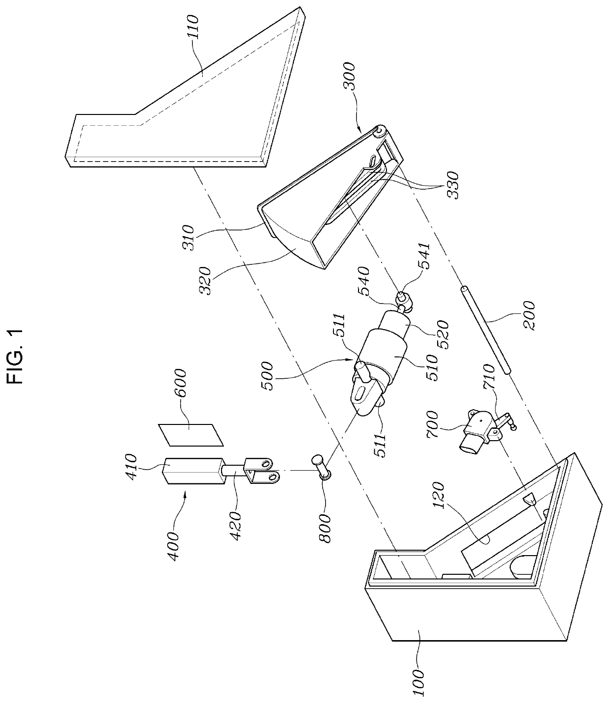
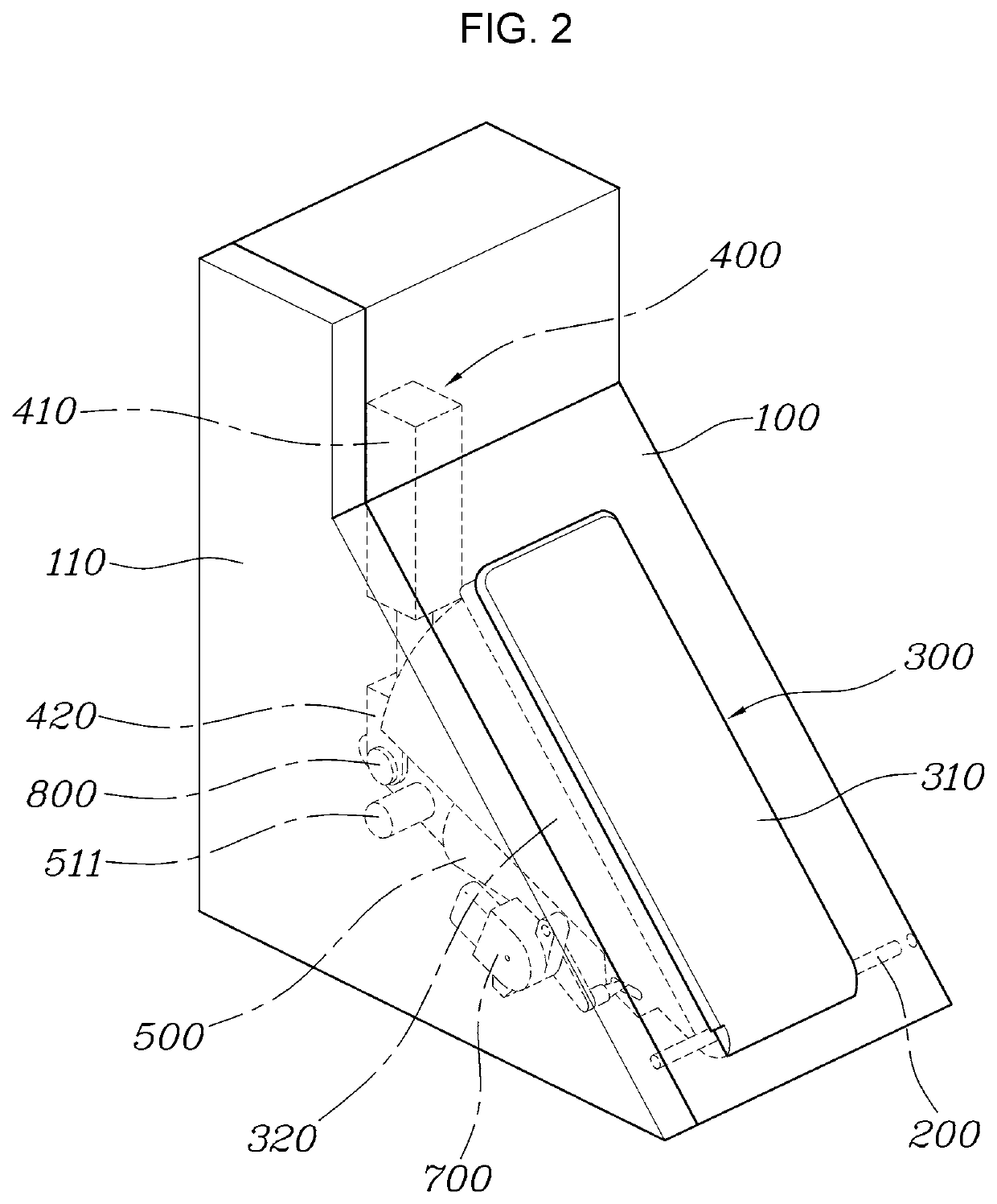
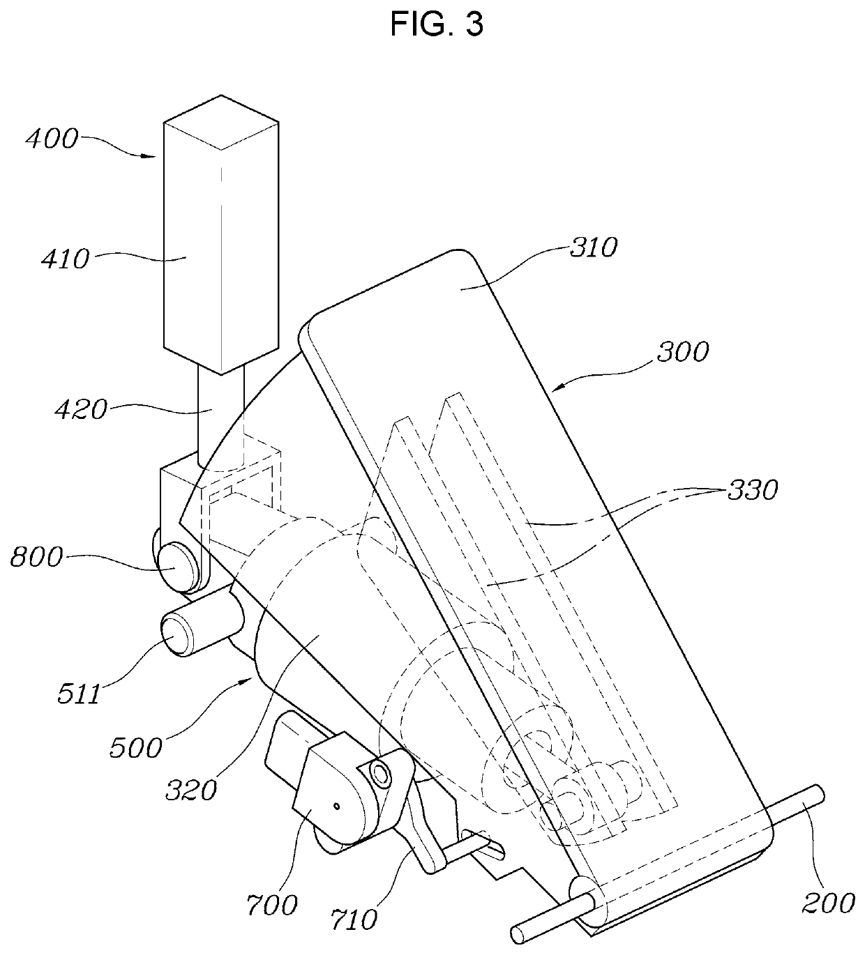
A foldable brake pedal apparatus of an autonomous vehicle, may include a pedal housing to be mounted in a space below a driver's seat; a pedal pad pivotably coupled to the pedal housing via a hinge pin, in a response to movement of s driver's foot, and configured to be selectively switchable to a hidden state in which the pedal pad is inserted into the pedal housing or a popped-up state in which the pedal pad protrudes from the pedal housing; an actuator fixed in the pedal housing, coupled to the pedal pad and configured to generate power to pivot the pedal pad to allow the pedal pad to be in the hidden state or in the popped-up state; and a high load spring module pivotably coupled to the pedal housing, having one end portion thereof and the other end portion connected to the pedal pad and the actuator, and configured to transmit the power of the actuator to the pedal pad.

Description

CROSS REFERENCE TO RELATED APPLICATION[0001]The present application claims priority to Korean Patent Application No. 10-2020-0047970 filed on Apr. 21, 2020, the entire contents of which is incorporated herein for all purposes by this reference.BACKGROUND OF THE INVENTIONField of the Invention[0002]The present invention relates to a foldable brake pedal apparatus of an autonomous vehicle, and more particularly, to a technology for a foldable brake pedal apparatus of an autonomous vehicle, in which, in a manual driving mode in which a driver directly drives an autonomous vehicle, a pedal pad protrudes from a pedal housing to be exposed to the driver to allow the driver to operate an autonomous vehicle, and in an autonomous driving mode, the pedal pad is inserted into the pedal housing to be blocked from being exposed to the driver to prevent an operation of the autonomous vehicle from being performed by the driver.Description of Related Art[0003]Autonomous vehicles are smart vehicles ...

Claims


Application Information

Patent Timeline
IPC IPC(8): B60R21/09B60T7/04B60T7/06G05G1/40G05G5/00G05G5/05G05G1/38G05G5/03G05G1/30G05G1/44G05G5/28
CPCB60T7/042B60R21/09B60T7/06G05G1/38G05G1/40G05G5/005G05G5/03G05G5/05B60T7/065G05G1/30G05G1/44G05G5/28B60T13/741B60W60/00133B60W60/0015B60W60/0053B60T2220/04
Inventor KIM, EUN SIKKIM, HYEON UKBYUN, SUNG IL
Owner HYUNDAI MOTOR CO LTD
Learn More