
Retrofit designs for steel beam-to-column connections

a technology of retrofit design and steel beam, which is applied in the direction of protective buildings/shelters, building types, constructions, etc., can solve the problems of compromising the strength and ductility of the connection, the design methodology of flange-welded-web-bolted steel beam-to-column connection that is widely used in the construction of steel moment frames, and should not be used in the design, so as to eliminate the shear in the beam flange and eliminate the large stress and strain

Active Publication Date: 2021-02-02
SEISMIC STRUCTURAL DESIGN ASSOC
View PDF19 Cites 0 Cited by
  • Summary
  • Abstract
  • Description
  • Claims
  • Application Information

AI Technical Summary

Benefits of technology

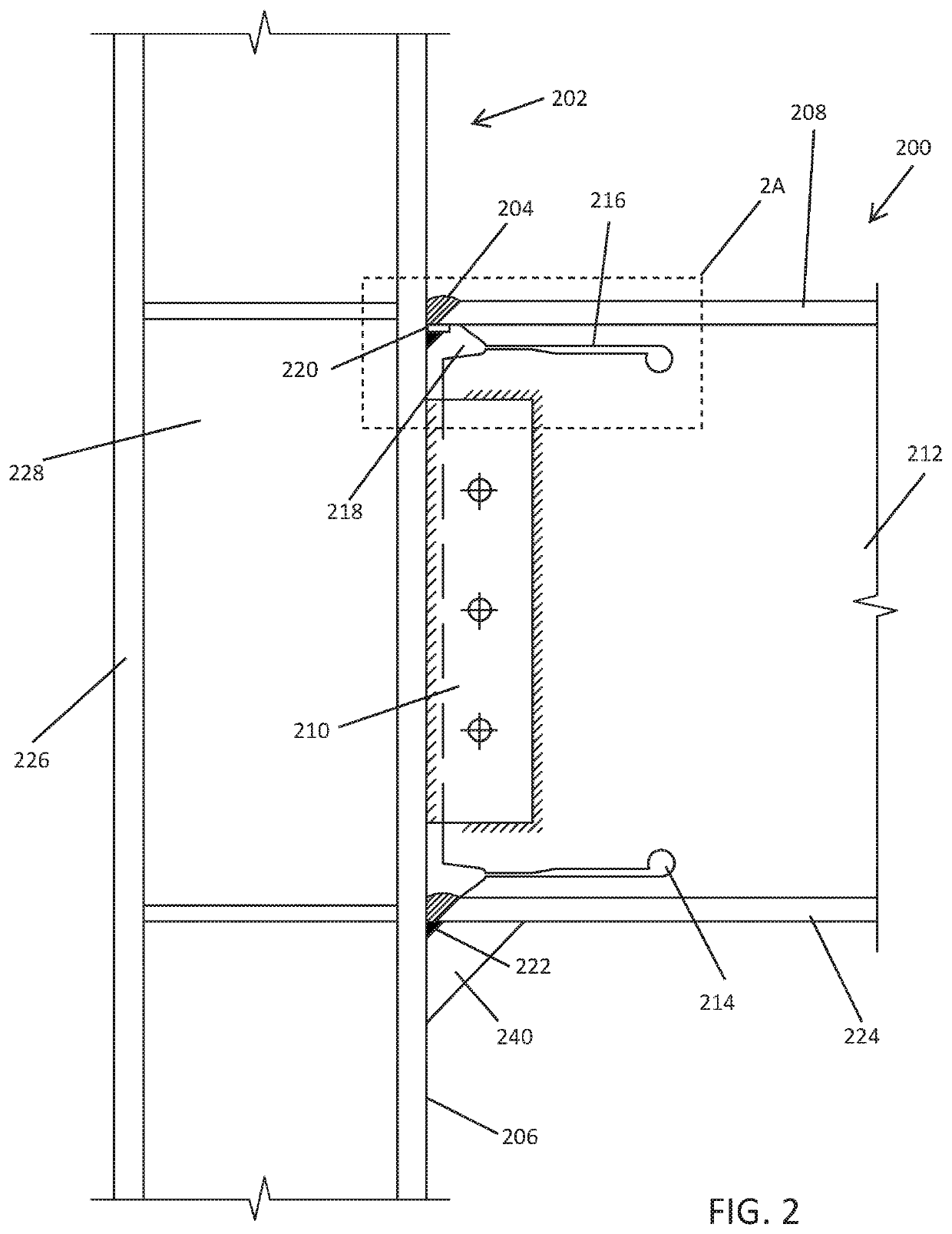
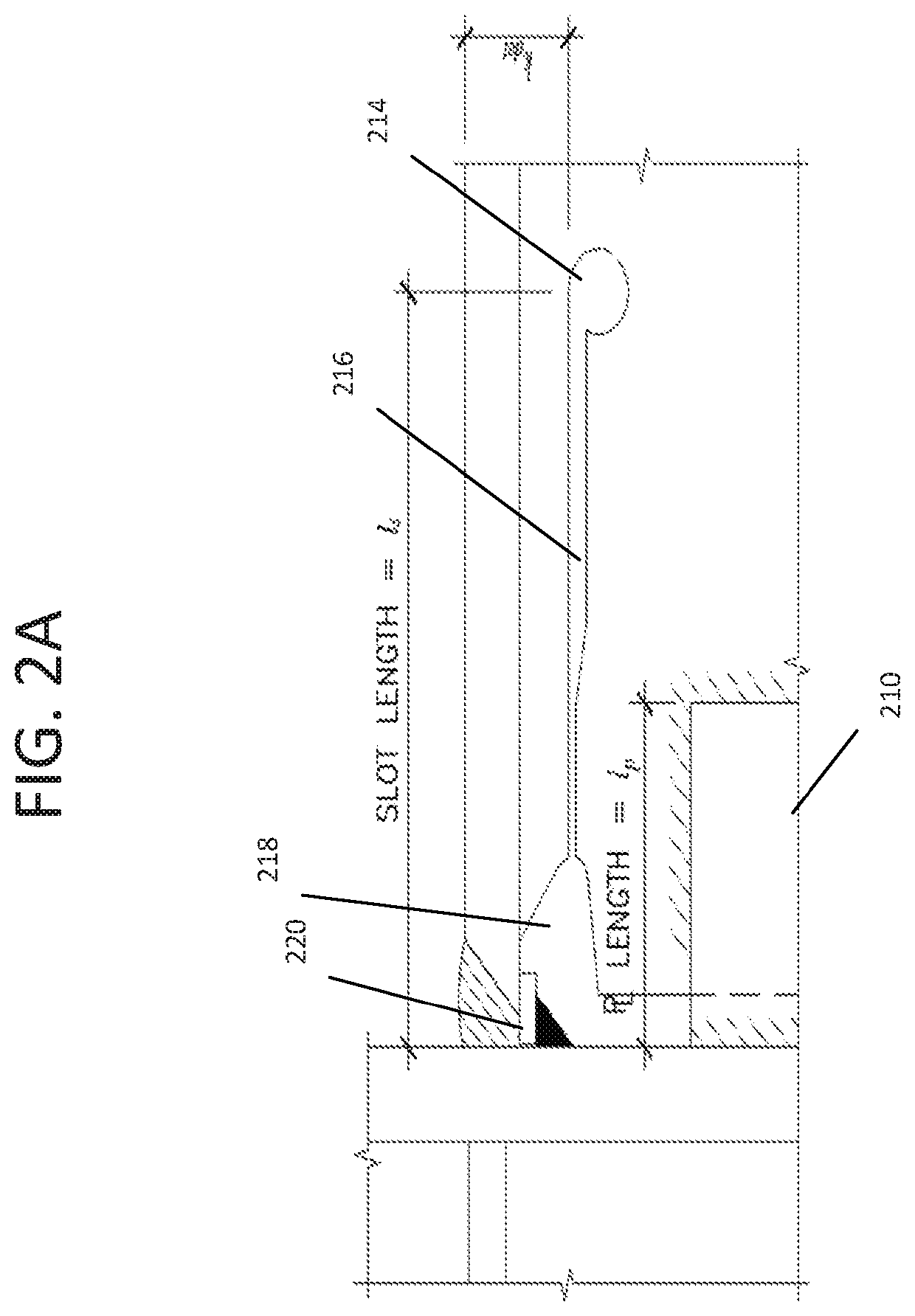
[0003]Embodiments of the present invention relate to systems and methods for creating beam connections that provide improvements over and, where necessary, repair of pre-Northridge connections by eliminating the shear in the beam flanges, as well as the large stress and strain concentrations in the beam flanges. Specifically, embodiments of the invention provide techniques for creating beam connections that utilize particular arrangements of beam web slots, beam flange reinforcing fins, and beam web welds to achieve these benefits. Using beam web slots and beam web welds as presented herein for existing pre-Northridge connections eliminates the shear in the beam flanges and eliminates the large stress and strain concentrations in the beam flanges. Embodiments of the invention provide methods for retrofitting existing pre-Northridge connections to utilize beam web slots and beam web welds, and beam flange reinforcing fins.

Problems solved by technology

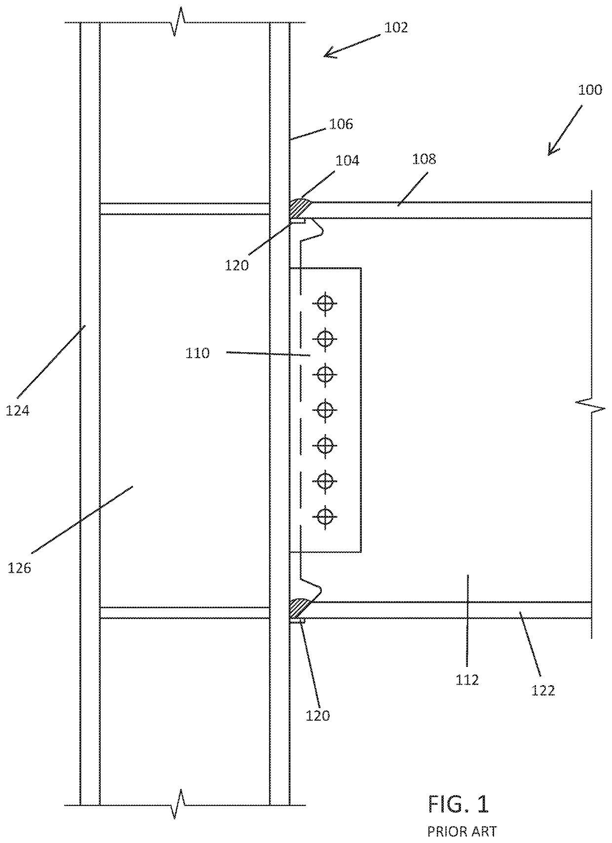
Extensive research by structural engineers has shown that the flange-welded-web-bolted steel beam-to-column connection design methodology that is widely used in the construction of steel moment frames is flawed and should not be used in the design of moment frames that are subject to seismic or large wind loads.
Because of this, the moment and shear in the beam flanges result in large variations in the stress and strain distributions across and through the beam flanges and welds in the connection which compromise the strength and ductility of the connection.

Method used


Image

  • Retrofit designs for steel beam-to-column connections
  • Retrofit designs for steel beam-to-column connections
  • Retrofit designs for steel beam-to-column connections

Examples


Embodiment Construction

[0013]The ensuing description provides exemplary embodiments only, and is not intended to limit the scope, applicability or configuration of the disclosure. Rather, the ensuing description of the embodiments will provide those skilled in the art with an enabling description for implementing multiple embodiments. It will be understood that various changes may be made in the function and arrangement of elements without departing from the spirit and scope of this disclosure.

[0014]As described above, the pre-Northridge connection that is commonly used in the construction of steel moment frames is flawed in that it relies upon an incorrect assumption that at the connection, the shear in the beam is totally resisted by the beam web and the moment in the beam is totally resisted by the beam flanges. Embodiments of the invention provide a slotted web retrofit design methodology that uses beam web slots to eliminate or reduce the beam flange moments and shears. This results in a near uniform...


PUM


Abstract

A method of retrofitting a pre-Northridge type steel beam-to-column connection, includes welding the web of the beam to a flange of the column and slotting the beam web in the region of the connection and near the beam flanges. Stress relief holes are made into the web of the beam and slots are cut into the web of the beam. A top backup bar is welded to the flange of the column and a bottom backup bar is removed from the flange weld to the column. The method includes back gouging the flange of the column at a position of the removed backup bar and welding a bottom flange of the beam to the flange of the column.

Description

CROSS-REFERENCE TO RELATED APPLICATIONS[0001]This application is continuation-in-part of U.S. patent application Ser. No. 16 / 397,868, entitled “RETROFIT DESIGNS FOR STEEL BEAM-TO-COLUMN CONNECTIONS”, which claims the benefit of U.S. Provisional Application No. 62 / 663,881, entitled “RETROFIT DESIGNS FOR STEEL BEAM-TO-COLUMN CONNECTIONS”, filed on Apr. 27, 2018, and U.S. Provisional Application No. 62,727,797, entitled “RETROFIT DESIGNS FOR STEEL BEAM-TO-COLUMN CONNECTIONS”, filed on Sep. 6, 2018, the entire contents of which are hereby incorporated by reference.BACKGROUND OF THE INVENTION[0002]Extensive research by structural engineers has shown that the flange-welded-web-bolted steel beam-to-column connection design methodology that is widely used in the construction of steel moment frames is flawed and should not be used in the design of moment frames that are subject to seismic or large wind loads. This connection, shown in FIG. 1, which was used extensively prior to the 1994 Nort...

Claims


Application Information

Patent Timeline
Patent Type & Authority Patents(United States)
IPC IPC(8): E04H9/02E04B1/24
CPCE04H9/027E04B1/2403E04H9/024E04B2001/2415E04B2001/2445E04B2001/2442
Inventor RICHARD, RALPH M.ALLEN, CLAYTON J.
Owner SEISMIC STRUCTURAL DESIGN ASSOC
Learn More