Clutch unit and motor vehicle drive train having a clutch unit of this type

a technology of clutch unit and drive train, which is applied in the direction of clutches, control devices, vehicle components, etc., can solve the problems of large structural space occupation and cost, and achieve the effect of saving structural space and cost, and reducing the number of sensors

Active Publication Date: 2021-02-02
MAGNA POWERTRIAN INC (US)
View PDF14 Cites 0 Cited by
  • Summary
  • Abstract
  • Description
  • Claims
  • Application Information

AI Technical Summary

Benefits of technology

[0006]It is an object of the invention to specify a clutch unit which is distinguished by a compact and cost-reduced construction in relation to the known clutch units. It is also an object of the invention to specify a particularly energy-efficient motor vehicle drivetrain, in particular an all-wheel-drive drivetrain, having a clutch unit of said type.
[0016]By means of the clutch unit according to the invention, it is possible, with only one sensor unit, to detect the clutch position and the clutch rotational speed in a simple manner, wherein the clutch rotational speed can be determined both in the first position of the counterpart element, that is to say when the clutch is open, and in the second position of the counterpart element, that is to say when the clutch is closed. In this way, it is possible in particular for control of the clutch unit to be simplified. Furthermore, the clutch unit is distinguished by a cost-reduced construction which takes up less structural space.
[0019]By means of the design of the motor vehicle drivetrain according to the invention, it is possible in particular to realize an energy-optimized and power-optimized all-wheel-drive drivetrain which is distinguished by a reduced number of sensors. In this way, both structural space and costs can be saved.

Problems solved by technology

The known designs of clutch unit are to be regarded as taking up a large amount of structural space and as being cost-intensive.

Method used


Image

  • Clutch unit and motor vehicle drive train having a clutch unit of this type
  • Clutch unit and motor vehicle drive train having a clutch unit of this type
  • Clutch unit and motor vehicle drive train having a clutch unit of this type

Examples


Embodiment Construction

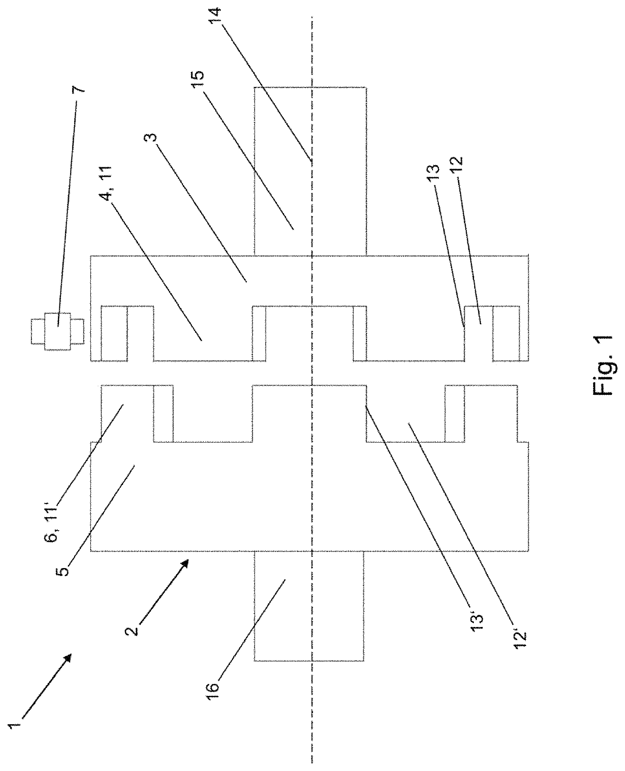
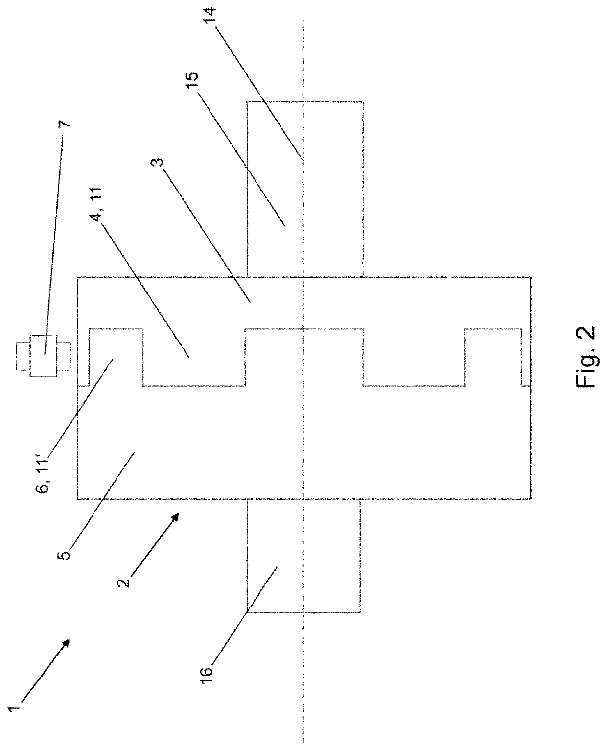
[0035]FIG. 1 and FIG. 2 each show a schematic illustration of an exemplary clutch unit 1 according to the invention.

[0036]The clutch unit 1 comprises a clutch 2 and a sensor unit 7.

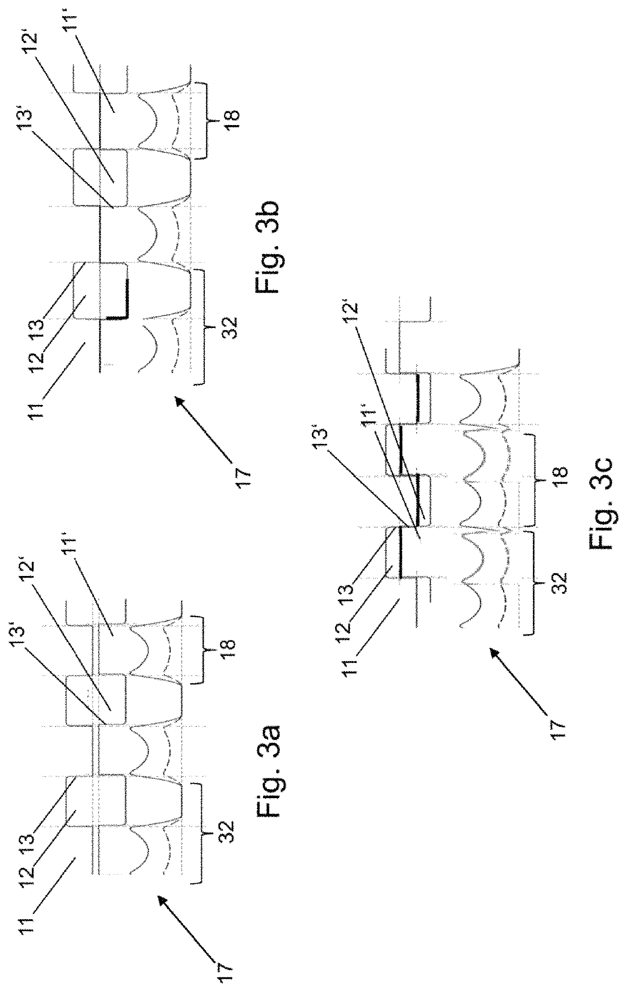
[0037]The clutch 1 is designed as a dog clutch and has two clutch members, specifically a coupling element 3 and a counterpart element 5. The coupling element 3 and the counterpart element 5 are designed so as to be couplable to one another in positively locking fashion. The positive locking between the coupling element 3 and the counterpart element 5 is realized by means of a counterpart toothing 6 formed on an end side of the counterpart element 5, which counterpart toothing engages into a toothing 4 of the coupling element 3, which toothing is formed on an end side, facing toward the counterpart toothing 6, of the coupling element 3. The toothing 4 and the counterpart toothing 6 extend in each case in opposite axial directions and each have a multiplicity of teeth 11, 11′ and spaces 12, 12′. Here, in e...


PUM


Abstract

The invention relates to a clutch unit for a motor vehicle, comprising: a clutch, the clutch having an axially stationary, rotatable coupling element with an axially extending toothing, and an axially displaceable, rotatable mating element with an axially extending mating toothing, the mating element being displaceable into a first position and a second position; and a sensor unit, the sensor unit being disposed radially in relation to the axial extension of the toothing of the coupling element such that the sensor unit senses the toothing of the coupling element. When the mating element is in the first position and when it is in the second position, the sensor unit detects a sensor signal via which the rotational speed of the coupling element and the first position of the mating element, the second position of the mating element, or a position of the mating element between the first position and the second position can be determined. The invention also relates to a motor vehicle drive train comprising a clutch unit of this type.

Description

CROSS-REFERENCE TO RELATED APPLICATIONS[0001]This application is a National Stage of International Application No. PCT / EP2017 / 065454, filed Jun. 22, 2017, which claims the benefit and priority to German Patent Application No. DE 10 2016 212 132.4 filed Jul. 4, 2016. The entire disclosures of each of the above applications are incorporated herein by reference.FIELD OF THE INVENTION[0002]The present invention relates to a clutch unit for a motor vehicle, comprising a clutch, wherein the clutch has an axially fixed, rotationally movable coupling element with an axially extending toothing and has an axially displaceable, rotationally movable counterpart element with an axially extending counterpart toothing, wherein the counterpart element is displaceable into a first position, specifically a position in which the counterpart element is not connected to the coupling element, and a second position, specifically a position in which the counterpart element is connected in positively lockin...

Claims


Application Information

Patent Timeline
Patent Type & Authority Patents(United States)
IPC IPC(8): F16D11/14B60K23/08
CPCF16D11/14B60K2023/0858F16D2300/18F16D2500/30408F16D2500/30415F16D2500/30401
Inventor EISL, THOMASJÄGER, DANIELTIGELHARDT, MARIOUNTERKOFLER, JOHANNES
Owner MAGNA POWERTRIAN INC (US)
Why Eureka
Try Eureka