
Telescopic adjuster

a technology of telescopic adjuster and telescopic rod, which is applied in the direction of rod connection, fastening means, and gearing, etc., can solve the problems of urgent problems to be solved, space limitation, and how to implement a telescopic adjuster with a relatively long stroke in a limited space, so as to achieve the effect of increasing the strok

Active Publication Date: 2021-02-02
PEGATRON
View PDF14 Cites 0 Cited by
  • Summary
  • Abstract
  • Description
  • Claims
  • Application Information

AI Technical Summary

Benefits of technology

[0006]The disclosure provides a telescopic adjuster capable of effectively increasing a stroke.
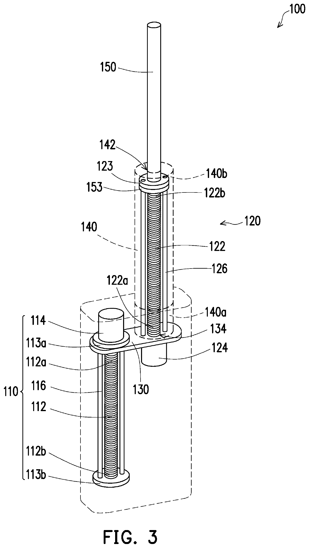
[0010]In one embodiment of the present invention, the aforementioned second linear actuator further includes a second motor and a pair of second guiding rod. The second motor is connected with the second screw to control the second screw to rotate, and the second guiding rod are located on two sides of the second screw and are fixed to the connecting platform. One end of the first outer cylinder tube is fixed to the connecting platform, while the other end of the first outer cylinder tube has an opening; and the second screw pushes up the second outer cylinder tube to extend out of the first outer cylinder tube from the opening. The telescopic adjuster further includes a third fixing ring, which is arranged at the end, relatively close to the connecting platform, of the second outer cylinder tube. The second guiding rod pass through the third fixing ring, and the second fixing ring and the third fixing ring may limit a moving distance of the second-outer cylinder tube through the second fixing ring.
[0012]Based on the above, the present invention provides the telescopic adjuster of a structure different from common structures. Through the change of the structure, the problems of the original stroke and the space limitation are improved, and the stroke of the outer cylinder tube may be increased under the same height space.

Problems solved by technology

However, a space limitation must be considered when the cylinder tube is selected.
Therefore, how to implement a telescopic adjuster having a relatively stroke in a limited space is an urgent problem to be solved.

Method used


Image

  • Telescopic adjuster
  • Telescopic adjuster
  • Telescopic adjuster

Examples


Embodiment Construction

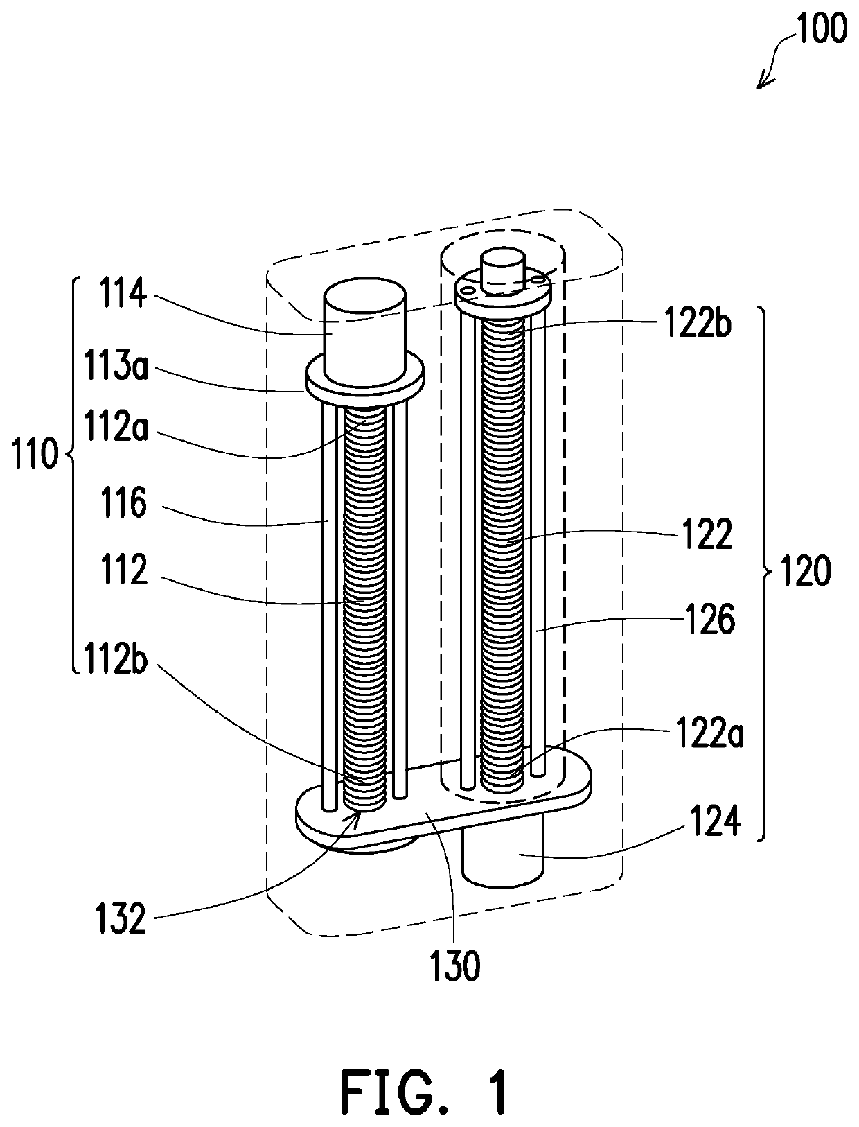
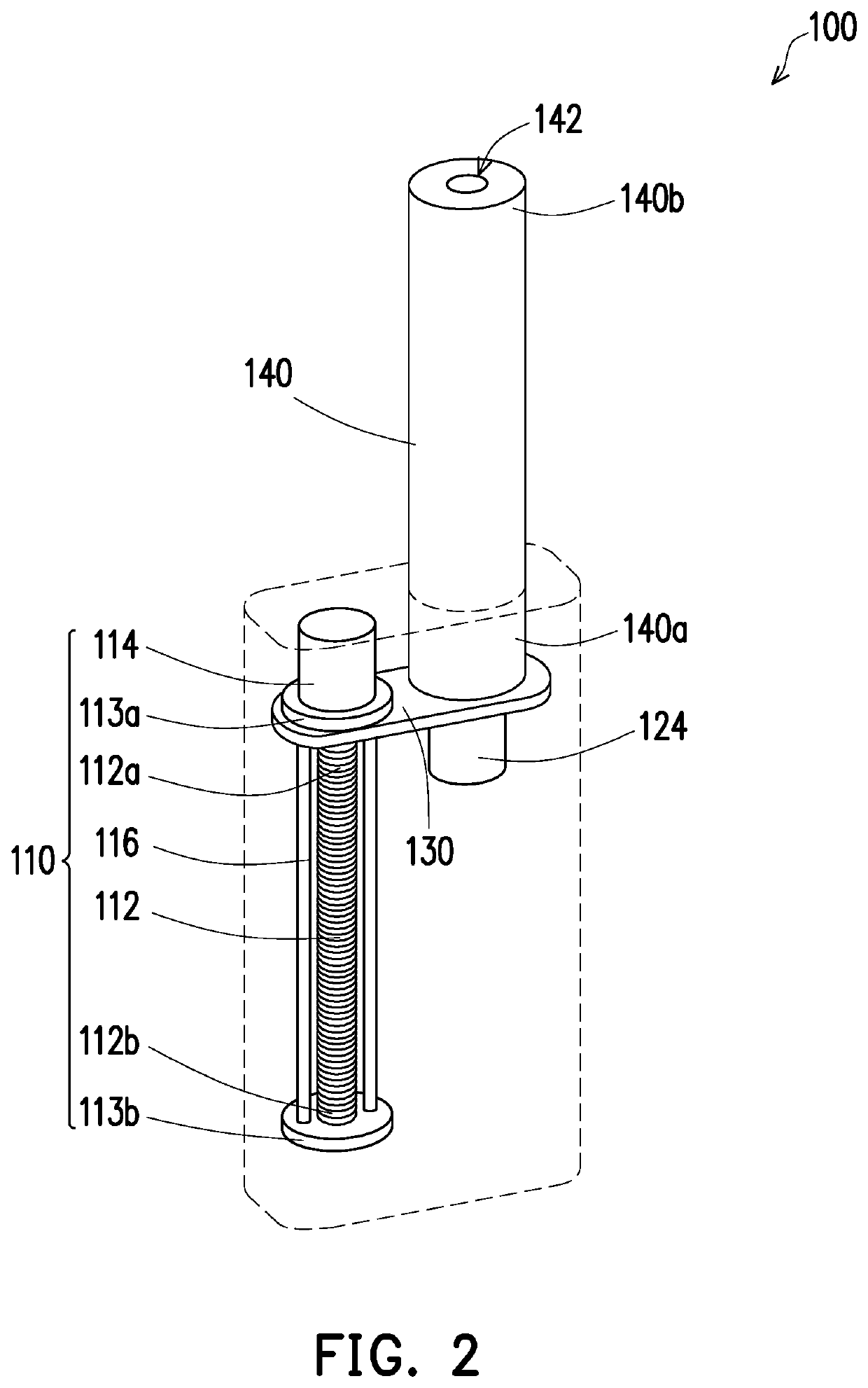
[0017]FIG. 1 is a schematic diagram of a telescopic adjuster of the present invention. FIG. 2 is a schematic diagram showing an extension of a first outer cylinder tube of the telescopic adjuster of FIG. 1. FIG. 3 is a schematic diagram showing an extension, out of the first outer cylinder tube, of a second outer cylinder tube of the telescopic adjuster. Referring to FIGS. 1, 2 and 3 together, a telescopic adjuster 100 of the present embodiment may be applied to equipment required to extend or retract, such as a neck of a robot or a telescope, according to requirements.

[0018]The telescopic adjuster 100 includes a first linear actuator 110, a second linear actuator 120, a connecting platform 130, a first outer cylinder tube 140 and a second outer cylinder tube 150.

[0019]The first linear actuator 110 includes a first screw 112 and a pair of first fixing rings 113a and 113b. The first fixing rings 113a and 113b are arranged at two respective ends of the first screw 112. The second line...


PUM


Abstract

A telescopic adjuster including first and second linear actuators, a connecting platform and first and second telescopic levers is provided. The first linear actuator includes a first screw and a pair of first fixing rings. The first fixing rings are arranged at two respective ends of the first screw. The second linear actuator includes a second screw and a second fixing ring. The second fixing ring is arranged at the end of the second screw, relatively away from the connecting platform. The first and second linear actuators are arranged on the connecting platform in parallel. The first screw pushes the connecting platform to move along the first screw, and the first fixing rings limit a movement of the connecting platform. The first and second telescopic levers are coaxially arranged.

Description

CROSS-REFERENCE TO RELATED APPLICATION[0001]This application claims the priority benefit of Taiwan application serial no. 107121586, filed on Jun. 22, 2018. The entirety of the above-mentioned patent application is hereby incorporated by reference herein and made a part of this specification.BACKGROUND1. Technology Field[0002]The present invention generally relates to a telescopic adjuster and, in particular, to a telescopic adjuster capable of effectively increasing a stroke.2. Description of Related Art[0003]A stroke size of a traditional telescopic adjuster depends on a length of an outer cylinder tube which is driven by a screw to rise up. If a longer stroke is required, a longer matched-cylinder tube is adopted.[0004]However, a space limitation must be considered when the cylinder tube is selected.[0005]Therefore, how to implement a telescopic adjuster having a relatively stroke in a limited space is an urgent problem to be solved.SUMMARY[0006]The disclosure provides a telescop...

Claims


Application Information

Patent Timeline
Patent Type & Authority Patents(United States)
IPC IPC(8): F16H3/06F16H27/02F16H29/02F16H29/20F16H25/20F16B7/10
CPCF16H25/2056F16B7/10F16H2025/204F16H25/20F16H2025/2053F16H2025/2075F16H25/2015F16H25/2018
Inventor TSAI, PEI-YINGHUNG, SHIH-WEICHUANG, WEN-CHANG
Owner PEGATRON
Learn More