Systems and methods for power production using a carbon dioxide working fluid

a working fluid and carbon dioxide technology, applied in steam engine plants, mechanical equipment, machines/engines, etc., can solve the problems of increasing costs due to the need for added equipment, requiring significant power consumption, and no longer having sufficient heat content in the exhaust stream of turbines

Active Publication Date: 2021-02-09
8 RIVERS CAPTTAL LLC
View PDF190 Cites 1 Cited by
  • Summary
  • Abstract
  • Description
  • Claims
  • Application Information

AI Technical Summary

Benefits of technology

[0006]The present disclosure relates to systems and methods for power production wherein a carbon dioxide (CO2) working fluid is utilized. The CO2 stream utilized as the working fluid is a recycled CO2 stream that is compressed, heated with the heat of combustion in a reactor (e.g., combustion of a hydrocarbon fuel or other fuel material), expanded for power production in a turbine, cooled in a recuperative heat exchanger, purified (e.g., by removal of water, excess carbon dioxide, or other materials), and then compressed and recycled by heating in the recuperative heat exchanger. In some embodiments, liquid water and high pressure CO2 resulting from the combustion of hydrogen and carbon that can be present in the fuel can be provided as separate products from the power cycle. The present systems and methods may be particularly defined in relation to the configuration of the CO2 stream compression system coupled with the configuration of the heat exchange system, particularly in the low temperature end of the recuperative heat exchanger. Such configurations beneficially can achieve and exceed efficiencies seen in known power cycles without any need for externally provided heat derived from adiabatic compression of gas streams.
[0013]The presently disclosed systems and methods beneficially can exhibit an overall efficiency that is at least as high as the prior art systems utilizing a recycled carbon dioxide working fluid stream, inclusive of systems having externally provided heat using indirect heat transfer from adiabatically compressed air in the cryogenic O2 plant or from an adiabatically compressed part of the recycle CO2 stream. The present systems and methods provide advantages including at least the elimination of all of the heat transfer systems requiring adiabatic CO2 recycle and cryogenic oxygen plant air compression and associated high pressure heat exchangers. This can lead to significant cost savings, simpler more compact plant layout, and simpler control systems. Further, the present systems and methods can allow the cryogenic air separation plant power requirement to be reduced by 15% to 20%, and the capital cost of the air separation plant with its standard air compressors will be much lower. Similarly the CO2 compression train can be simplified. The overall cost of a commercial plant utilizing systems and methods as described herein can be significantly lower with the elimination of the adiabatic compressor gas coolers and all of their piping and other systems, and the plot layout will be significantly reduced in area and complexity. There will be positive effects on the overall power system efficiency and a significant reduction in the cost of electricity produced.
[0032]the temperature of the oxidant stream entering section three of the recuperator heat exchanger is adjusted to minimize the cold end temperature difference of the recuperator heat exchanger;

Problems solved by technology

This increase means that the turbine exhaust stream no longer has sufficient heat content in the low temperature end of the recuperator heat exchanger to provide more than about half the heat required to raise the temperature of the total recycle high pressure CO2 stream plus the oxygen required for fuel gas combustion.
Known methods for providing the additional heat, however, have various drawbacks, including requiring significant power consumption, increasing costs due to the need for added equipment, and increasing process complexity.
For example, known systems have provided added heating to a power production system from an air separation plant, but utilizing such source of added heating can require specialized controls, particularly when demand for power changes rapidly.

Method used


Image

  • Systems and methods for power production using a carbon dioxide working fluid
  • Systems and methods for power production using a carbon dioxide working fluid
  • Systems and methods for power production using a carbon dioxide working fluid

Examples


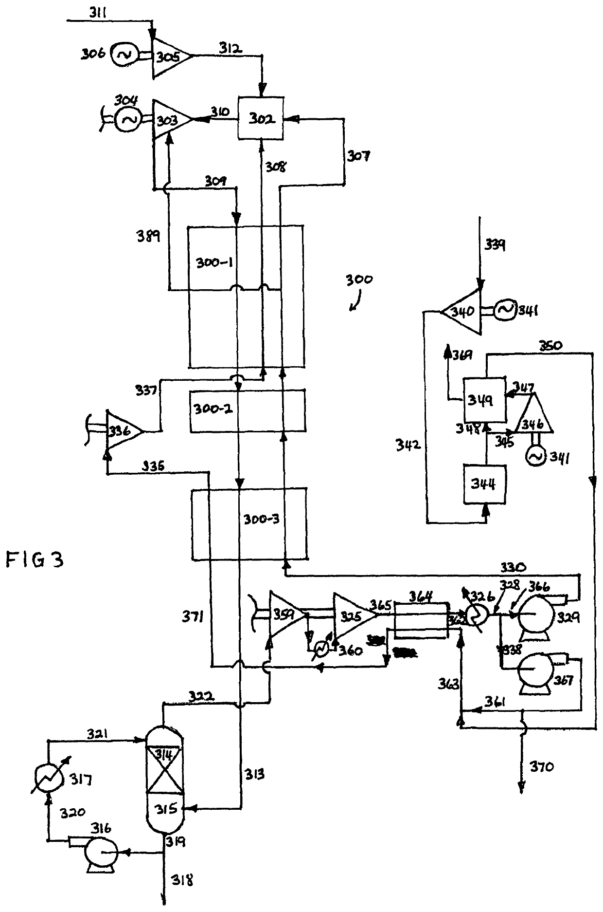
example 1 (embodiment according to fig.3)

Example 1 (Embodiment According to FIG. 3)

[0080]

Turbine inlet condition1212° C. and 300 barTurbine cooling and seal gas flow10% of turbine outlet flowTurbine outlet condition720° C. and 20 barOxygen flow rate4120.9 metric tons per dayTurbine power492.7MwParasitic power for O2 plus143.79MwCH4 and CO2 compressionNet power output348.97MwMethane fuel power potential595MwRecycle CO2 at 3043,098,320Kg / Hrbar entering recuperator HxNet efficiency58.65%(LHV)

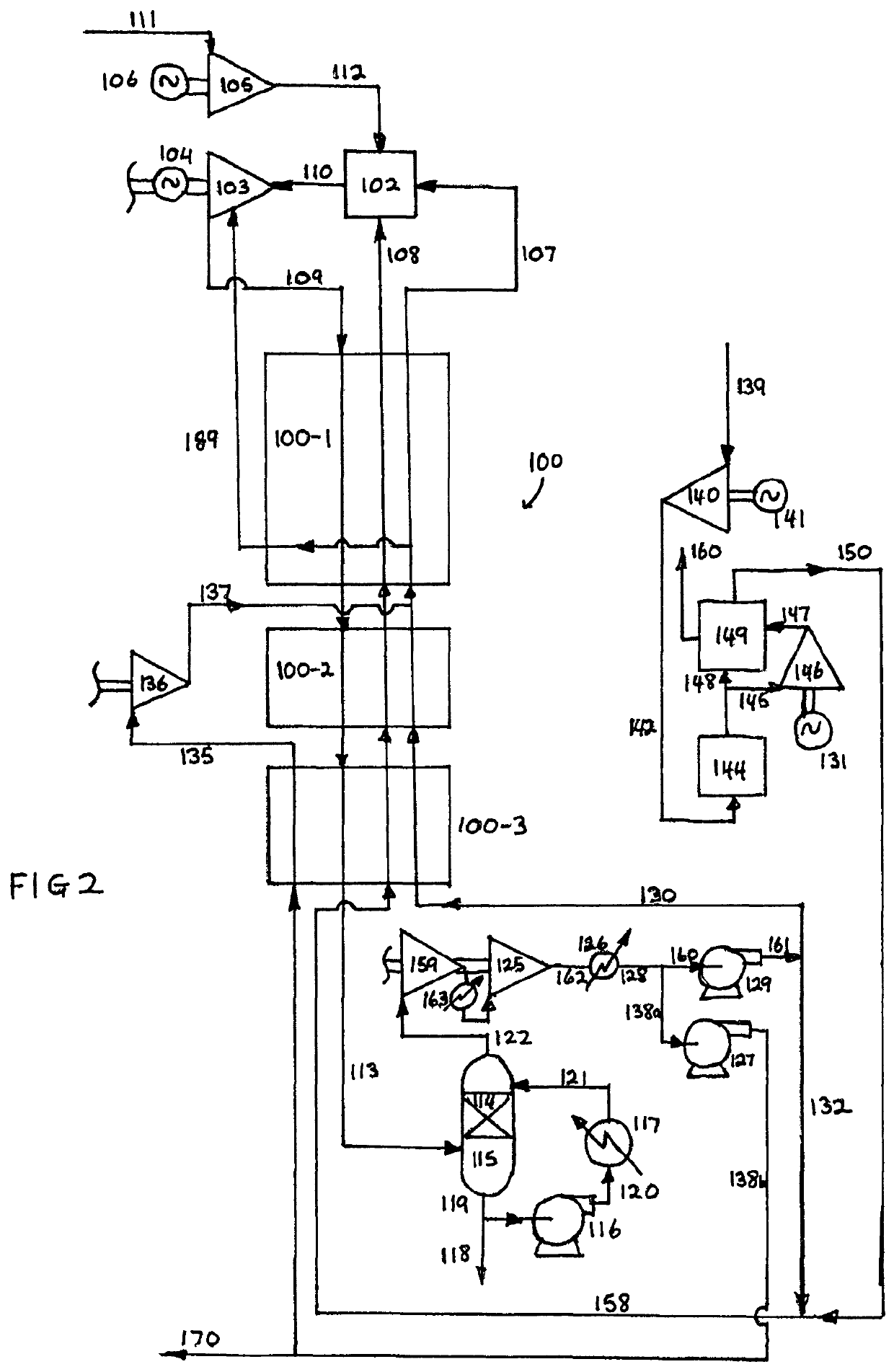
example 2 (embodiment according to fig.2)

Example 2 (Embodiment According to FIG. 2)

[0081]

Turbine inlet condition1520° C. and 300 barTurbine cooling and seal gas flow10% of turbine outlet flowTurbine outlet condition707° C. and 4 barTurbine power904.4MwParasitic power for O2 plus255.1MwCH4 and CO2 compressionNet power output649.3MwMethane fuel power potential927.21MwRecycle CO2 at 3043,131,657Kg / Hrbar entering recuperator HxNet efficiency70.0%(LHV)


PUM


Abstract

The present disclosure relates to systems and methods for power production utilizing a recirculating working fluid. In particular, a portion of the recirculating working fluid can be separated from the main stream of recirculating working fluid as a bypass stream that can be compressed for adding heat to the system.

Description

CROSS-REFERENCE TO RELATED APPLICATIONS[0001]The present application claims priority to U.S. Provisional Patent Application No. 62 / 637,542, filed Mar. 2, 2018, the disclosure of which is incorporated herein by reference.FIELD OF THE DISCLOSURE[0002]The present disclosure relates to systems and methods for power production using a carbon dioxide working fluid.BACKGROUND[0003]Utilization of CO2 (particularly in supercritical form) as a working fluid in power production has been shown to be a highly efficient method for power production. See, for example, U.S. Pat. No. 8,596,075 to Allam et al., the disclosure being incorporated herein by reference, which describes the use of a directly heated CO2 working fluid in a recuperated oxy-fuel Brayton cycle power generation system with virtually zero emission of any streams to the atmosphere. In order to increase process efficiency, such systems and methods have typically utilized a significant heat input below a temperature of about 400° C. ...

Claims


Application Information

Patent Timeline
Patent Type & Authority Patents(United States)
IPC IPC(8): F02C3/34F01K23/10F01K25/10
CPCF02C3/34F01K23/10F01K25/103B01D2257/504B01D2257/80
Inventor ALLAM, RODNEY JOHN
Owner 8 RIVERS CAPTTAL LLC
Why Eureka
Try Eureka