Fingerprint authorisable device

a fingerprint authorisation and fingerprint technology, applied in the field of fingerprint authorisation devices, can solve the problems of fingerprint authorisation failing or not being possible, fingerprint damage or other damage to user's fingerprints, sensor damage or other inoperableness, etc., and achieve the effect of reducing the likelihood of such errors and balancing scanning errors

Active Publication Date: 2021-02-16
ZWIPE
View PDF25 Cites 0 Cited by
  • Summary
  • Abstract
  • Description
  • Claims
  • Application Information

AI Technical Summary

Benefits of technology

[0015]To avoid any need for communication of the fingerprint data outside of the device then the device may be able to self-enroll, i.e. the control system may be arranged to enroll an authorised user by obtaining fingerprint data via the fingerprint sensor. This also has advantages arising from the fact that the same sensor with the same geometry is used for the enrolment as for the fingerprint authorisation. The fingerprint data can be obtained more consistently in this way compared to the case where a different sensor on a different device is used for enrolment. With fingerprint biometrics, one problem has been that it is difficult to obtain repeatable results when the initial enrolment takes place in one place, such as a dedicated enrolment terminal, and the subsequent enrolment for matching takes place in another, such as the terminal where the matching is required. The mechanical features of the housing around each fingerprint sensor must be carefully designed to guide the finger in a consistent manner each time it is read by any one of multiple sensors. If a fingerprint is scanned with a number of different terminals, each one being slightly different, then errors can occur in the reading of the fingerprint. Conversely, if the same fingerprint sensor is used every time then the likelihood of such errors occurring is reduced.
[0063]The invention may also include a method of manufacturing a smartcard. This may consist of providing features as in the first aspect or the fourth aspect. The manufacturing method may also include providing any or all of the optional features discussed above. The method may include programming the processor to function as discussed above. To enhance the distinctions in vibrational patterns and hence allow for greater differences in accelerometer output between cards manufactured using the same process that are exposed to identical movements, then the manufacturing method may include varying the location of the accelerometer and / or adding mass / stiffness elements with differing characteristics and / or at differing locations to the cards so that each individual card has a unique vibration pattern. The method may optionally include adding a mass and / or stiffness element to the card, for example on a circuit board of the card, with the mass and / or stiffness element being selected from a set of elements with differing mass and / or stiffness characteristics. This allows for the added mass and / or stiffness element to be placed at the same location, which can allow for easier manufacture, whilst ensuring variable effects on the movement of the card since the mass and / or stiffness of the added element will vary. Alternatively or additionally a mass and / or stiffness element may be added to the card at a location that varies for each card. This could use an identical mass and / or stiffness element for each card, or the mass and / or stiffness element being selected from a set of elements with differing mass and / or stiffness characteristics.

Problems solved by technology

In some cases a fingerprint authorisation may fail or may not be possible.
For example the user's fingerprints may be damaged by injury, or covered up.
The sensor may also be damaged or might otherwise be inoperable.
Another situation that can arise with fingerprint sensors is a failure to enroll.
This is a fundamental issue with a small percentage of the population, who have fingerprints that for some reason cannot be registered using some or all sensors, and it also arises when people have missing or damaged fingers.
In existing fingerprint authorisable devices this presents a major problem, and often means that an alternative device must be provided for some users.

Method used


Image

  • Fingerprint authorisable device
  • Fingerprint authorisable device
  • Fingerprint authorisable device

Examples


Embodiment Construction

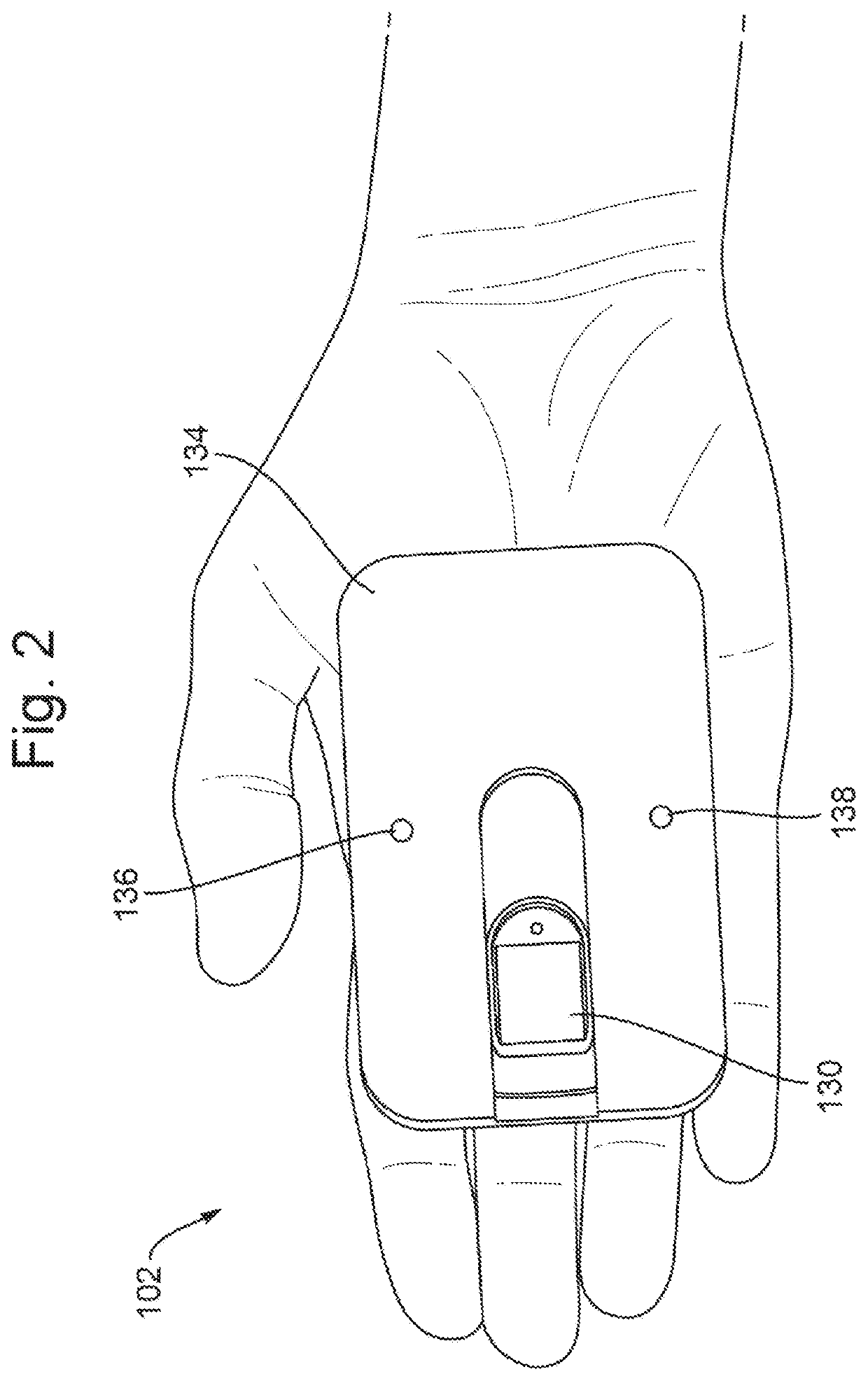
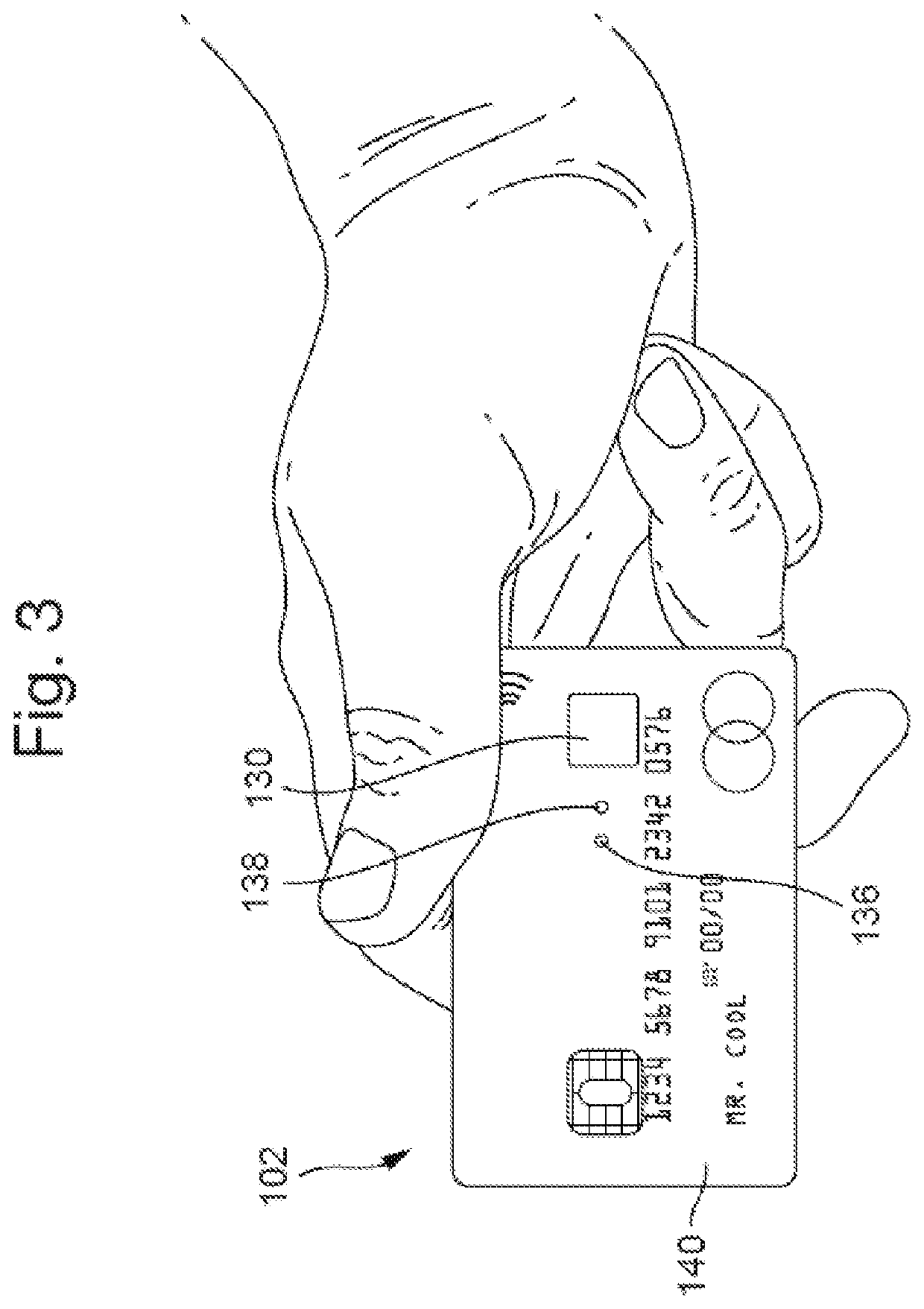
[0069]By way of example the invention is described in the context of a fingerprint authorised smartcard that includes contactless technology and uses power harvested from the card reader. These features are envisaged to be advantageous features of one application of the proposed fingerprint failure feature, but are not seen as essential features. The smartcard may hence alternatively use a physical contact and / or include a battery providing internal power, for example. The fingerprint failure feature can also be implemented with appropriate modifications in any other device or system that uses fingerprint authorisation.

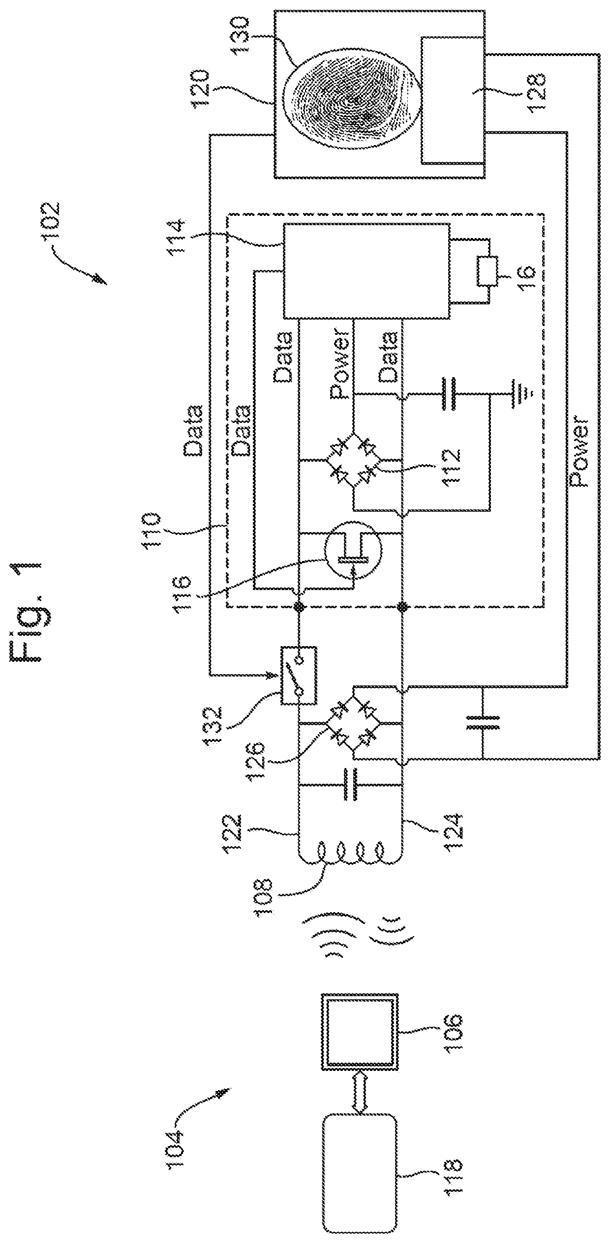
[0070]FIG. 1 shows the architecture of a smartcard 102 that is provided with the proposed fingerprint failure feature. A powered card reader 104 transmits a signal via an antenna 106. The signal is typically 13.56 MHz for MIFARE® and DESFire® systems, manufactured by NXP Semiconductors, but may be 125 kHz for lower frequency PROX® products, manufactured by HID Global ...


PUM


Abstract

A fingerprint authorisable smartcard may include a fingerprint sensor for obtaining fingerprint data from a user's finger or thumb, and a control system for controlling the smartcard. The control system may be arranged to provide access to one or more functions of the smartcard in response to identification of an authorised fingerprint and the control system further may include a fingerprint failure feature in which a non-fingerprint authorisation can act to at least partially replace the fingerprint authorisation such that the control system may be arranged to provide access to at least some of the one or more functions of the smartcard when a user is identified via the non-fingerprint authorisation. The non-fingerprint authorisation may require an interaction with the fingerprint authorisable smartcard by the user, the interaction including one or more action(s) detected via the fingerprint sensor.

Description

RELATED APPLICATIONS[0001]The present application is a continuation of U.S. application Ser. No. 16 / 081,608, filed on Aug. 31, 2018, now pending, which, in turn, is a National Phase application of International Application No. PCT / EP2017 / 054778, filed on Mar. 1, 2017. U.S. application Ser. No. 16 / 081,608 and International Application No. PCT / EP2017 / 054778 are incorporated herein by reference in full.TECHNICAL FIELD[0002]The present invention relates to a fingerprint authorisable device and to a method for controlling a fingerprint authorisable device.BACKGROUND OF THE INVENTION[0003]Fingerprint authorised devices such as smartcards are becoming increasingly more widely used. Smartcards for which biometric authorisation has been proposed include, for example, access cards, credit cards, debit cards, pre-pay cards, loyalty cards, identity cards, cryptographic cards, and so on. Smartcards are electronic cards with the ability to store data and to interact with the user and / or with outs...

Claims


Application Information

Patent Timeline
Patent Type & Authority Patents(United States)
IPC IPC(8): G06K19/07G06F21/32
CPCG06K19/0718G06F21/32G06K19/0719G06F3/0488
Inventor HUMBORSTAD, KIM KRISTIAN
Owner ZWIPE
Why Eureka
Try Eureka