
Long-stator linear motor

a linear motor and long-stator technology, applied in electric vehicles, railway tracks, dynamo-electric machines, etc., can solve the problems of not being able to equip the transport path, transport vehicles can “derail”, and the required pressure force cannot be achieved, so as to achieve a very high pressure force in the single comb area and the design of the passive part is slim.

Active Publication Date: 2021-02-16
B&R IND AUTOMATION GMBH
View PDF15 Cites 1 Cited by
  • Summary
  • Abstract
  • Description
  • Claims
  • Application Information

AI Technical Summary

Benefits of technology

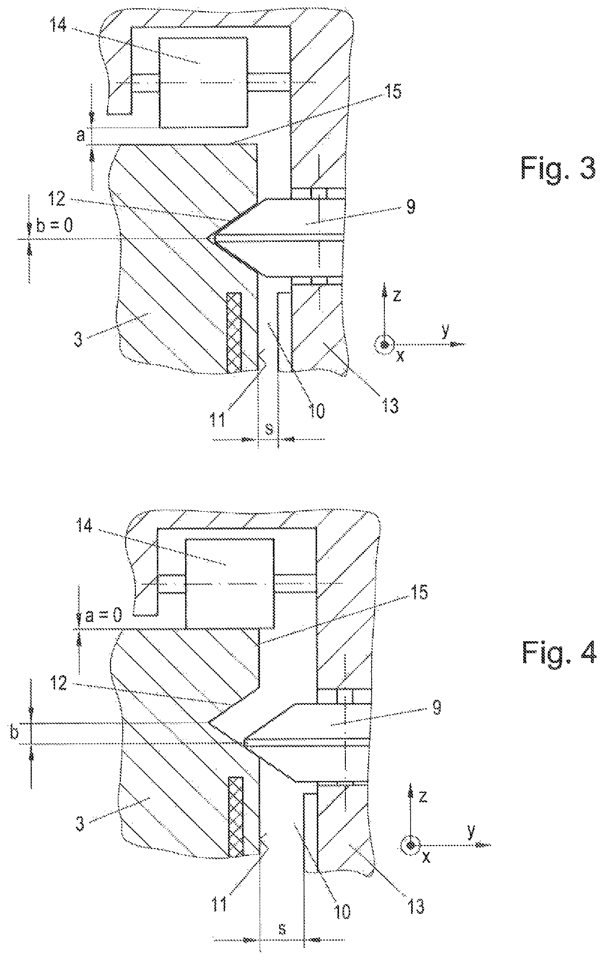
[0007]Advantageously, the auxiliary guide member can be spaced apart from the auxiliary guide, when the profile member is centered at or in the guide track. As a result, the auxiliary guide does not generate interfering friction in track sections, in which the pressure force is sufficiently high.
[0009]Advantageously, the first running member can be attached to the guide surface. The combination of profile member and running member facilitates the insertion of the transport vehicle and ensures a defined distribution of the pressure force.
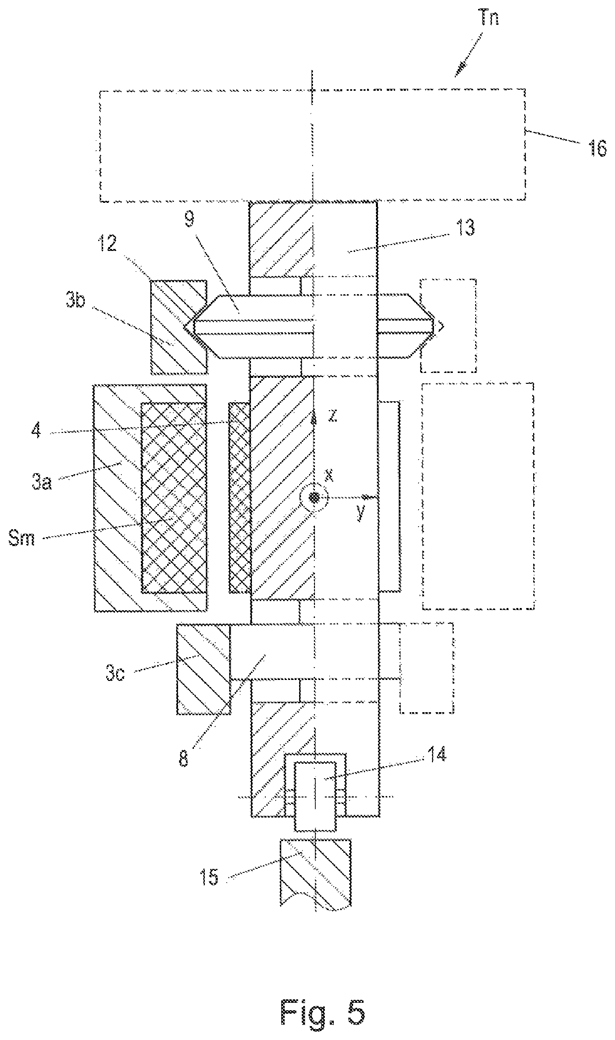
[0013]In an advantageous manner, at least one profile member can be designed as a combined sliding / rolling member, the rotational axis of which is arranged centrally in the passive part, wherein the profile member protrudes from both sides of the passive part in the transverse direction. This allows for a very slim design of the passive part. Furthermore, the fact is utilized that the pressure force in the single comb area is very high, wherein the profile member acts as a pure rolling member, and that the pressure force is very low in the double comb areas, wherein the profile member can thus act as a sliding member on both sides.

Problems solved by technology

However, it is disadvantageous that the transport vehicles can “derail” if the pressure force is too low or the bearing load is too great, i.e., the profile member moves out of the guide track, wherein the transport vehicle subsequently falls off of the holding structure.
It is therefore not possible to equip the transport path with drive coils arranged on both sides because with such an arrangement, which is also called a double comb arrangement, the required pressure force would not be achieved.
However, an arrangement on both sides is required especially in the area of switches, particularly if the switches are supposed to be operable without mechanically moved adjusting elements.
As a result, the transport vehicle can also travel through areas of the transport path, in which the pressure force of the profile member would inherently not be sufficient to keep the transport vehicle safely in the track.

Method used


Image

  • Long-stator linear motor
  • Long-stator linear motor
  • Long-stator linear motor

Examples


Embodiment Construction

[0024]The particulars shown herein are by way of example and for purposes of illustrative discussion of the embodiments of the present invention only and are presented in the cause of providing what is believed to be the most useful and readily understood description of the principles and conceptual aspects of the present invention. In this regard, no attempt is made to show structural details of the present invention in more detail than is necessary for the fundamental understanding of the present invention, the description taken with the drawings making apparent to those skilled in the art how the several forms of the present invention may be embodied in practice.

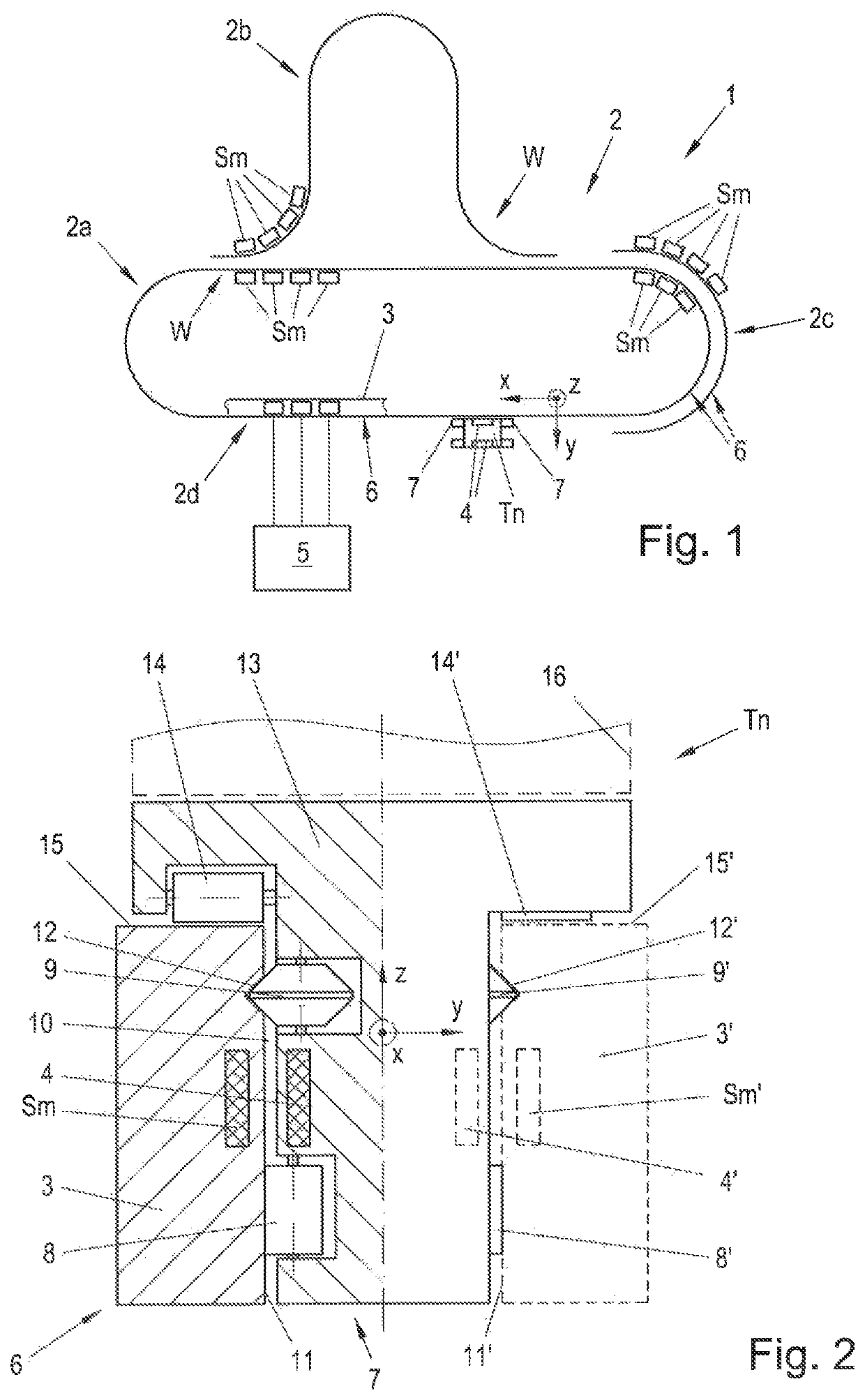
[0025]FIG. 1 shows an exemplary conveying application with a long-stator linear motor 1 with a transport path 2, along which a number of transport vehicles Tn, with n≥1, can be moved. For the sake of simplicity, FIG. 1 only shows a single transport vehicle Tn, wherein, as a rule, a multiplicity of transport vehicles Tn, f...


PUM


Abstract

Long-stator linear motor with vehicle arranged for movement along transport path. Motor includes holding structure(s) having drive coils, on which passive part of vehicle is arranged; and guide surface and guide track running along path. Passive part has first drive magnet(s) arranged parallel to guide surface with air gap. Vehicle has first profile member(s) arranged on guide track and positioned by pressing force acting in transverse direction onto guide track with respect to an ascending direction running normally to movement direction and transverse direction. First running member(s) support passive part on holding structure against attractive force acting between drive magnets and drive coils to ensure the air gap. Vehicle has first auxiliary guide member(s) which, interacting with an auxiliary guide on holding structure at least in divergence and / or convergence areas of path, delimits movement of vehicle in a positive and / or negative ascending direction at least on one side.

Description

CROSS-REFERENCE TO RELATED APPLICATIONS[0001]The present application claims priority under 35 U.S.C. § 119(a) of European Patent Application No. 18184227.9 filed Jul. 18, 2018, the disclosure of which is expressly incorporated by reference herein in its entirety.BACKGROUND1. Field of the Invention[0002]The invention relates to a long-stator linear motor having a transport path, along which at least one transport vehicle is movably arranged in the movement direction, wherein the long-stator linear motor comprises at least one holding structure having drive coils, on which a passive part of the transport vehicle is arranged, wherein the long-stator linear motor has a guide surface extending along the transport path, and a guide track extending along the transport path, wherein the passive part comprises at least one first drive magnet which is arranged parallel to the guide surface while leaving an air gap, wherein the transport vehicle has at least one first profile member which is a...

Claims


Application Information

Patent Timeline
Patent Type & Authority Patents(United States)
IPC IPC(8): H02K41/03B65G35/08
CPCH02K41/031B65G35/08B65G21/2009B65G54/02H02K41/02B60L13/003B60L13/03B60L13/06E01B25/32
Inventor HOECK, MARTINDICKER, ALEXANDER
Owner B&R IND AUTOMATION GMBH
Learn More