Surgical planning and method

a technology for knee replacement and surgical planning, applied in the field of total knee replacement surgery, can solve the problems of reducing the mechanical performance of the prosthetic components, unbalancing the forces exerted between the tibial and femoral prosthetic components, and the forces at the interface between the prosthetic components and their respective bones, and further knee problems

Active Publication Date: 2021-03-02
DEPUY (IRELAND) LTD
View PDF88 Cites 0 Cited by
  • Summary
  • Abstract
  • Description
  • Claims
  • Application Information

AI Technical Summary

Benefits of technology

[0057]A sixth aspect of the invention provides a medium bearing user readable instructions enabling the user to carry out the method of the second aspect of the invention. The medium may also bear user readable instructions for carrying out any of the preferred features of the second aspect of the invention. The medium may bear an indication of the first pre-selected range of values and the second pre-selected range of values. The medium may include one or more first fields where a user can record data. The data may be anatomical data derived from the patient. The anatomical data may include the angle of the femoral mechanical axis, the angle of the tibial mechanical axis, the angle between the femoral mechanical axis and the tibial mechanical axis, the angle of the joint line, the angle between the joint line and the femoral mechanical axis and / or the angle between the joint line and the tibial mechanical axis. The medium may include one or more second fields where a user can record the result of a calculation. The result of the calculation may be a value of an angle.

Problems solved by technology

On the other hand, if an anatomy based philosophy is adopted to the surgical procedure, so that the femoral implant and tibial implant are placed so that the post-operative alignment of the leg is similar to the pre-operative alignment of the leg, for varus or valgus patients, this results in the load line passing medially or laterally of the knee centre and therefore unbalancing the forces exerted between the tibial and femoral prosthetic components and also the forces at the interfaces between the prosthetic components and their respective bones.
Hence, although such an approach preserves the leg alignment of the patient, it can reduce the mechanical performance of the prosthetic components and also lead to further knee problems.

Method used


Image

  • Surgical planning and method
  • Surgical planning and method
  • Surgical planning and method

Examples


Embodiment Construction

[0070]The following detailed description sets forth numerous specific details to provide a thorough understanding of the invention. However, those skilled in the art will appreciate that the invention may be practiced without these specific details. In other instances, well known methods, procedures, components, instruments or implants have not been described in detail so as not to obscure the invention.

[0071]In the Figures like reference numerals are used for like elements unless indicated otherwise or the context requires otherwise.

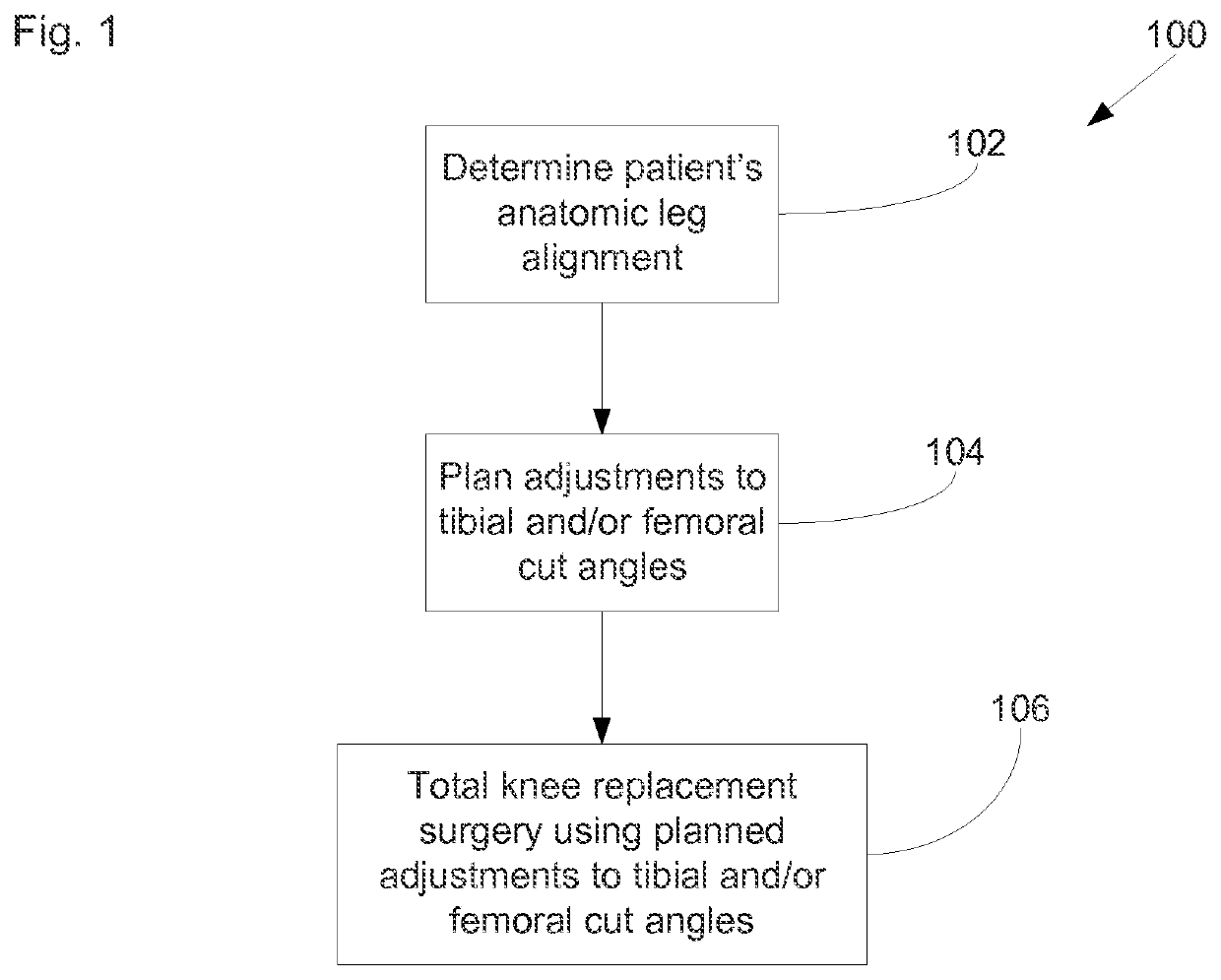
[0072]With reference to FIG. 1, there is shown a high level flowchart illustrating various stages of an overall method 100 of preparing for, planning and conducting total knee replacement surgery 100. Aspects of the invention may reside in the overall method 100, the individual stages thereof, combinations of the individual stages and combinations of sub-stages of the stages illustrated in FIG. 1.

[0073]An initial stage 102 of the overall method involves...


PUM


Abstract

Methods and apparatus for planning and / or carrying out a total knee replacement surgical procedure on a knee of a leg of a patient are described. Anatomical data for the leg of the patient is obtained, which allows the femoral mechanical axis, the tibial mechanical axis and the joint line of the knee to be determined. A planned proximal tibial cut angle and a planned distal femoral cut angle are determined. A total knee replacement procedure is carried out on the knee of the patient, wherein a distal femoral cut is made using the planned distal femoral cut angle and a proximal tibial cut is made using the planned proximal tibial cut angle.

Description

CROSS REFERENCE TO RELATED APPLICATION[0001]This application is a National Stage 35 U.S.C. 371 of International Patent Application PCT / US2015 / 051672 filed Sep. 23, 2015, claiming priority to U.S. Patent Application 62 / 054,604, filed Sep. 24, 2014.BACKGROUND OF THE INVENTION[0002]The present invention relates to total knee replacement surgery and in particular to methods of planning total knee replacement surgery and also to a workflow for a surgical method to execute a surgical plan.[0003]Various surgical techniques for total knee replacement are generally known and used. They typically involve replacement of a distal part of the patient's femur with a femoral prosthetic implant or component and replacement of a proximal part of the patient's tibia with a tibial prosthetic implant or component. An aspect of the surgical procedure is preparing the distal part of the femur and proximal part of the tibia to provide resect bone surfaces on which the respective implants are placed. The h...

Claims


Application Information

Patent Timeline
Patent Type & Authority Patents(United States)
IPC IPC(8): A61B34/10A61B17/15A61B17/56A61F2/38A61F2/46A61B34/20
CPCA61B34/10A61B17/155A61B17/157A61B2017/564A61B2034/104A61B2034/105A61B2034/108A61B2034/2046A61F2/38A61F2002/4633
Inventor SHUPE, SARAH J.ROCK, MICHAEL JOSEPHWOLFSON, DAVID ROBERTFUSARI, GIANPAOLOTOMOS, HAWYS ELERIMATTHEWS, ROBERT EDWARDNAYBOUR, JOHNHELDRETH, MARK
Owner DEPUY (IRELAND) LTD
Why Eureka
Try Eureka